On carburetor vehicles, the valve is controlled by a vacuum applied to it, which ensures that the action of the valve matches the load on the engine by the action of the control valves.
The valves open and close very quickly. The incoming air flow through the air ducts maintains the optimal ratio of the gas mixture entering the carburetor, depending on the load on the engine.
On vehicles with fuel injection, the on-board computer contains information about the ideal position of the EGR valve for different engine operating modes. The EGR valve opening degree sensor transmits information to the on-board computer, which, in turn, using this information and signals from other sensors, determines the time for the electric pulse to be supplied to the control solenoid. The solenoid opens the control valve and applies vacuum to the EGR valve. Both systems include means to limit EGR operation when the engine is cold. Since the combustion temperature of the air-fuel mixture is relatively low, the amount of nitrogen oxides formed is much less. In this case, the EGR system is blocked to improve cold engine performance.
System action
For vehicles with fuel injection
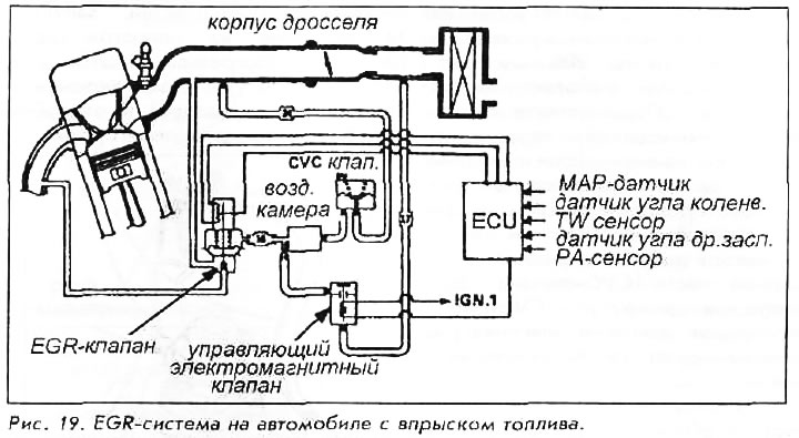
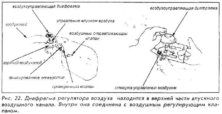
The EGR valve does not just open or close, but changes the degree of opening with a vacuum applied to the diaphragm valve, which is maximally opened by a vacuum action of 200 mm Hg. The on-board computer sets the position of the control solenoid valve, which regulates the opening of the EGR valve according to the programmed program. Balances the action of the pilot solenoid valve. Constant volume control valve (CVC valve), ensuring a constant supply of vacuum, and thus ensuring the accuracy of EGR control in various conditions. An air chamber between the control solenoid and the CVC valve acts as an expansion tank, dampening vacuum fluctuations. The control solenoid valve, CVC valve and air chamber are located in the control box on the bulkhead.
Testing
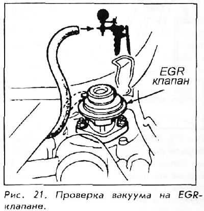
1. First check that all vacuum hoses and electrical contacts are in good condition. If the engine does not idle, disconnect the vacuum hose to the EGR valve and plug it. If the engine starts at idle, then the problem is in the EGR control system. Start the engine and wait until the fan comes on (the engine is warm). Disconnect the vacuum hose to the EGR valve and connect a hand pump with a pressure gauge to the valve to the hose.
2. With the engine idling, apply a vacuum to the EGR valve. The motor should stop and the valve should hold the vacuum! If not, replace the EGR valve.
3. Connect a hand pump with a gauge to the vacuum hose from the control solenoid valve and restart the engine at idle. Vacuum should not be determined.
4. If vacuum is detected at the EGR valve at idle, check the wires to the control solenoid valve. One of the wires should have 12V at any time the engine is running. The ground wire goes to the onboard computer that controls the opening of the solenoid valve, controlling the main circulation. Switch off the ignition and, using a digital ohmmeter, check the wire between the computer and the solenoid valve for a shorted circuit. If the wire is OK, then either the on-board computer receives an incorrect signal from the sensor, or the computer itself is out of order.
5. The vacuum going to the control solenoid should be about 200mmHg when the engine is idling. Connect the pump with a pressure gauge to the hose coming from the air chamber. If the pressure gauge reading is not as specified, check the vacuum at the outlet of the CVC valve. Full manifold vacuum must be detected at the inlet of the CVC valve. If the air chamber or CVC valve is leaking pressure or malfunctioning, it cannot be repaired.
6. To check the EGR valve opening degree sensor, turn off the ignition and disconnect the wires to the EGR valve. Then turn on the ignition and check if there is a voltage of 5V at the sensor terminals. Turn off the ignition, connect an ohmmeter to the center and either end terminal of the sensor, and change the pressure on the EGR valve with a hand pump. The resistance should change as the valve opens and closes.
Carburetor engines
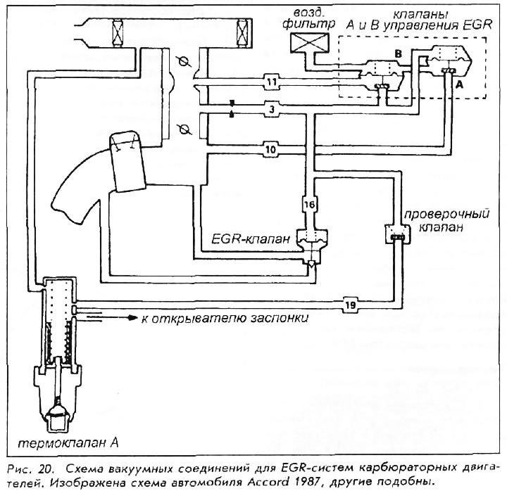
This system is controlled by a pair of control valves actuated by changes in system vacuum. A change in throttle vacuum opens valve A, which allows manifold vacuum to open valve B. With valve B open, some of the vacuum is released into the carburetor passages and valve A begins to close and the EGR valve opens. Ultimately, the balance is achieved by the mutual influence of the collector and transmitted vacuum. This links the opening of the EGR valve to the opening of the throttle valve and therefore the load on the engine. When the engine is cold or the vehicle is not moving, the EVAP shutoff solenoid stops vacuum from reaching valve B, preventing it from reaching the EGR valve. The system is much easier to test than to comprehend. With the exception of the shut-off solenoid valve, the system is completely mechanical. All malfunctions are somehow related to a leak or clogged vacuum hose, or a defective EGR valve.
Testing
1. With the engine cold, connect a pressure gauge to the EGR valve vacuum hose and run the engine at 3000 rpm. Vacuum should not be determined. If a vacuum registers, check the purge control system. Start the engine at idle, let it warm up to the optimum temperature (before turning on the radiator fan) and open the control box on the partition.
2. Remove the top vacuum hose from the shutoff solenoid valve and valve cover. Check the vacuum in the hose to the EGR valve in the following modes: in idle mode (no vacuum);
- in the mode of rotation of the motor shaft 3000 rpm (vacuum 51-152 mmHg);
- in 3000 rpm motor rotation mode with number 11 vent hose blocked. (vacuum less than 51 mm Hg.);
- deceleration (there shouldn't be a vacuum).
3. To check the EGR valve, plug the vacuum hose and connect a hand pump to the valve. Create a vacuum of about 150 mmHg. when the engine is idling. The engine should stall and vacuum should be held, indicating that the diaphragm is intact. If the engine does not stall, then either the valve does not open, or there is an obstruction in the vacuum supply system.
Catalytic converter
The most visible part of the emission control system is the catalytic converter. Its function is to combine unburned hydrocarbons and carbon monoxide (NS and CO) with oxygen to produce carbon dioxide. It also binds nitrogen oxides. The catalyst operates in a very narrow range of air-fuel mixture concentration. The oxygen sensor in the exhaust system transmits information about the concentration of O2 in the form of an electrical voltage to the on-board computer, which constantly adjusts the ratio of fuel and air in the air-fuel mixture to ensure the optimal composition of the gas mixture supplied to the catalyst. It should be noted that this process is carried out both on carburetor engines and on engines with fuel injection. The oxygen sensor is the main feedback element to the carburetor or control computer.
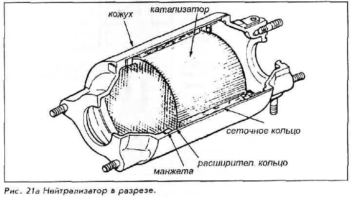
It is a completely passive device with no actuators or sensors. Contrary to popular belief in the late 70s, the device does not affect the operation of the engine until the catalyst melts and causes high resistance to the exhaust gases. If this is suspected, the catalyst can be removed and tested. With a simple look inside, one can assess the integrity of the honeycombs in the ceramic blocks. If some of them have melted and can cause resistance to exhaust gases, then this will be clearly visible. On some vehicles the catalytic converter is mounted directly on the exhaust manifold, on some it is further down in the exhaust system, but always in front of the muffler.
The only condition that is necessary for the normal operation of the catalyst is the use of unleaded gasoline. It is not adapted to the action of additives in leaded gasoline and will quickly lose its properties. All Honda engines are designed to run on unleaded gasoline and do not require leaded fuels to increase the octane rating. The quality of gasoline is achieved by perfect oil sublimation technology.