HondaBook.ru
Auto companies Volkswagen Auto companies Ford Auto companies Lada Auto companies Skoda Auto companies BMW Auto companies Mazda Auto companies Peugeot
English Русский
Български
Беларускі
Український
Српски
Hrvatski
Română
Polski
Slovenský
Magyar
Bookmark Contacts Sitemap   


Accord Civic Fit / Jazz CR-V HR-V Others Articles
Civic 3 and 4 (1983-1991) Civic 5 and 6 (1991-2000) Civic 6 (1995-2000) Civic 7 (2000-2005) Civic 8 (2005-2011)

Evaporative Emissions (EVAP) System — Component Testing and Replacement (Honda Civic 6)

  • Main
  • Honda Civic
  • 6 (1995-2000)
  • Power unit
  • Engine management systems
  • Evaporative Emissions (EVAP) System — Component Testing and Replacement
0
Contents: General information ⇊ Examination ⇊

General information


The system accumulates fuel vapors that accumulate while the vehicle is parked and ensures that they are discharged into the intake manifold for combustion during normal engine operation.

Any EVAP system necessarily includes a special adsorber filled with activated carbon, which actually collects fuel vapors. The method of removing vapors from the adsorber may vary depending on the design of a specific system. The following will allow the reader to understand in sufficient detail the operating principles of any type of EVAP system.

Note: The design described does not necessarily correspond exactly to the design of the system installed in a particular vehicle, but the operating principle is common to all models equipped with a fuel injection system. In case of any deviations, check the information provided on the VECI label.


The fuel filter cover is equipped with a two-way safety valve. In the event of a system failure, the valve ensures the removal of fuel vapors into the atmosphere.

Another two-way shut-off valve is installed on the fuel tank and provides regulation of the removal of fuel vapors into the carbon adsorber depending on the pressure/vacuum differences associated with temperature changes.

After passing through the two-way valve, fuel vapors enter the charcoal adsorber through the ventilation hoses, where they accumulate during the entire idle period.

When the engine is started, the purge solenoid valve of the adsorber remains closed until it warms up to a certain temperature, allowing the purge diaphragm valve to open due to the increase in the depth of vacuum in the intake manifold. From the adsorber, fuel vapors are blown out through the diaphragm valve into the intake manifold, from where they enter the combustion chambers, where they are burned out during normal engine operation.


Examination


Note: A complete inspection of the EVAP system is beyond the skill level of the average DIY mechanic. Fortunately, the EVAP system, like all other emission control systems, is covered by an additional 5-year/50,000-mile warranty. The most common EVAP system failures are due to a damaged canister or a failing vacuum hose.


Vacuum hoses


1. First of all, always check the condition of the vacuum hoses, damage or disconnection of which is most often the cause of system failure (please refer to the hose routing diagram on your vehicle's VECI label). Replace damaged hoses if necessary.

Purge control solenoid valve


1. The purge control solenoid valve removes accumulated vapors from the carbon canister by creating a vacuum in the intake manifold. The valve provides a vacuum when the engine is warm and remains closed when the engine is cold.

2. Make sure that the engine temperature does not exceed the temperature indicated on the solenoid valve:
  • 73°C for 1994 and 1995 models.
  • 68°C for models from 1996 onwards.

68°C for models from 1996 onwards.


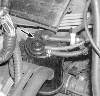
3. Locate the purge hose at the top of the carbon canister (see accompanying illustration). For assurance, refer to the hose routing diagram on the VECI label.


4. Having found the necessary hose, disconnect it from the adsorber and connect it to the vacuum gauge. Start the engine at idle speed - there should be no vacuum.

5. Wait until the engine warms up – now the vacuum should appear.

6. If the test results are negative, locate the purge control solenoid valve on the intake manifold and disconnect the wiring from it. Disconnect the vacuum hoses and connect a piece of rubber hose to one of the valve fittings.

7. Using jumper wires, connect the valve directly to the battery. Try to blow through the valve through the hose. When the battery is connected, the valve should be open and freely blown through; when disconnected, it should be closed (some models use the opposite valve operating scheme).

8. If the test results are negative, replace the solenoid valve.

Two-way valve


1. Remove the fuel filter cover.
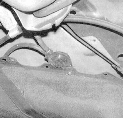
1. Remove the fuel filter cover.


2. Disconnect the fuel vapor line from the gas tank and connect the tee to a vacuum pump and vacuum gauge (see accompanying illustration).

3. Slowly and continuously increasing the vacuum depth, monitor the vacuum gauge readings. The vacuum should instantly stabilize at 5.1÷15.2 mm Hg. If the valve opens before the required vacuum depth is reached, replace it.


4. Switch the vacuum pump to the pressure fitting. Increase the pressure in the line and read the vacuum gauge. The pressure should stabilize in the range of 10.2÷35.6 mm Hg. (the valve is open).

5. If the valve opens before the required vacuum depth is reached, replace it.

Carbon adsorber ventilation shut-off valve


1. To determine if your vehicle is equipped with a canister vent shutoff valve, look at the top of the canister. If there is a 2-pin electrical connector on the cover, then the valve is present.

2. Follow the hose from the valve down to the three-way valve, assembly from the canister. Disconnect the hose from the three-way valve and connect it to the vacuum pump.

3. Remove the shut-off valve from the adsorber without disconnecting the electrical wiring and vacuum pump from it.

4. Turn on the ignition (without starting the engine) and create a vacuum in the hose. If the valve holds a vacuum, disconnect the electrical connector. If the valve still remains closed, replace it.
This article is available at: russian, bulgarian, belarusian, ukrainian, serbian, croatian, romanian, polish, slovak, hungarian
This information has been verified: Timofey Goryachev
Share with friends:
◀ Previous
Civic 6: Engine management systems
Next ▶

Exhaust Gas Recirculation (EGR) System — Component Checking and Replacement
Controlled Crankcase Ventilation (PCV) System
Intake Air Bypass System — Checking and Replacing the IAB Valve Diaphragm
Checking and replacing the fast idle speed (FIT) temperature sensitive valve
Idle Speed Control System — IAC Valve Check and Replacement
Catalytic Converter — Checking Condition and Replacement
See also other articles from Honda manuals:
Evaporative Emissions (EVAP) System — General Information, Testing,… Honda Accord 6 (1997-2002)
Headlight range correction system Honda Fit 1 (2001-2008)
Fuel Evaporative Emissions (EVAP) System Honda CR-V 2 (2002-2006, petrol)
Fuel Evaporative Emissions (EVAP) System Honda HR-V 1 (1998-2006, petrol)
Active Engine Mount Control System Component Locations Honda Avancier 1 (1999-2003, petrol)
Link in different formats to this article
Comments and feedback from visitors
No comments yet


How much will 32 + 18 ?


Civic 8 (2005-2011) 
  • General information
  • Technical data
  • Governing bodies
  • Driving and maintenance
  • Power unit
  • Gasoline engines (L13A)
  • Gasoline engines (R18A)
  • Diesel engines (N22A)
  • Cooling and lubrication (L13A)
  • Cooling and lubrication (R18A)
  • Cooling and lubrication (N22A)
  • Injection system (gasoline)
  • Injection system (diesel)
  • Toxicity reduction system
  • Troubleshooting
  • Transmission
  • Clutch and drive shafts
  • Mechanical gearbox
  • Chassis and running gear
  • Suspension and wheels
  • Steering
  • Brake system
  • Body and interior
  • Exterior (external elements)
  • Doors, locks and windows
  • Electrical equipment
  • Equipment and devices
  • Headlights and lighting
  • Power devices
  • Electrical circuits
Civic 7 (2000-2005) 
  • General information
  • User manual
  • Maintenance
  • Power unit
  • Engines D15B and D17A
  • K20A Engines
  • Overhaul engine
  • Cooling system
  • Lubrication system
  • Fuel injection system
  • Toxicity reduction system
  • Engine electrical equipment
  • Transmission
  • Clutch
  • Manual gearbox
  • Automatic gearbox
  • Variator (CVT)
  • Drive shafts
  • Chassis and running gear
  • Car suspension
  • Steering
  • Brake system
  • Body and interior
  • Exterior (external elements)
  • Interior (internal elements)
  • Doors, locks and windows
  • Heater and air conditioner
  • Manual air conditioner
  • Automatic air conditioner
  • Security system
  • Electrical equipment
  • Equipment and devices
  • Headlights and lighting
  • Windscreen wipers
  • Audio system
  • Electrical diagrams
Civic 6 (1995-2000) 
  • General information
  • Introduction to guide
  • User manual
  • Maintenance
  • Power unit
  • Engine in car (Civic)
  • Engine in car (Integra)
  • Engine overhaul
  • Cooling and heating
  • Power and exhaust systems
  • Engine electrical equipment
  • Engine management systems
  • Transmission
  • Manual gearbox
  • Automatic transmission (AT/CVT)
  • Clutch and drive shafts
  • Chassis and running gear
  • Brake system
  • Car suspension
  • Steering
  • Body and interior
  • Exterior (external elements)
  • Interior (internal elements)
  • Doors, locks and windows
  • Electrical equipment
  • Equipment and devices
  • Electrical circuits
Civic 5 and 6 (1991-2000) 
  • Power unit
  • SOHC engines
  • DOHC engines
  • Engine overhaul
  • Cooling and lubrication system
  • Intake and exhaust system
  • Fuel injection system (SOHC)
  • Fuel injection system (DOHC)
  • Carburetor
  • Transmission
  • Clutch
  • Manual gearbox S4C
  • Manual gearbox S40
  • Automatic gearbox
  • Drive shafts
  • Chassis and running gear
  • Car suspension
  • Steering
  • Brake system
  • Body and interior
  • Body elements
  • Heater and air conditioner
  • Electrical equipment
  • Power devices
  • Equipment and instruments
  • Electrical circuits
Civic 3 and 4 (1983-1991) 
  • General information
  • Maintenance
  • Power unit
  • Engine in a car
  • Engine overhaul
  • Cooling system
  • Power and exhaust system
  • Engine electrical equipment
  • Emission control system
  • Transmission
  • Mechanical gearbox
  • Automatic gearbox
  • Clutch and drive shafts
  • Four-wheel drive
  • Chassis and running gear
  • Brake system
  • Car suspension
  • Steering
  • Body and interior
  • Body elements
  • Electrical equipment
  • Equipment and devices
  • Electrical circuits
HondaBook.ru © 2018–2026 • Mobile version • Sitemap: EN BG BY UA RS HR RO PL SK HU • Feedback • Driver Information • Search system • Bookmark
Accord 3 (1985-1989) • Accord 6 (1997-2002) • Civic 3 and 4 (1983-1991) • Civic 5 and 6 (1991-2000) • Civic 6 (1995-2000) • Civic 7 (2000-2005) • Civic 8 (2005-2011) • Fit 1 (2001-2008) • CR-V 1 (1995-2001) • CR-V 2 (2002-2006) • HR-V 1 (1998-2006) • Avancier 1 (1999-2003) •
 
This website uses cookies to ensure proper functioning. By clicking "OK," you agree.