
Examination
1. TPS is mounted on the throttle body and connected to the throttle shaft. Based on the analysis of the signals from the TPS, the PCM determines the exact current position of the damper, due to the degree of depressing the gas pedal by the driver. The failure of the sensor can lead to uncontrolled emissions of fuel injectors and a violation of the stability of the engine speed. When a TPS malfunction is detected, the code P0122 or P0123 is entered into the memory of the self-diagnosis system (see Section On-Board Diagnostic System (OBD) - the principle of operation and fault codes).
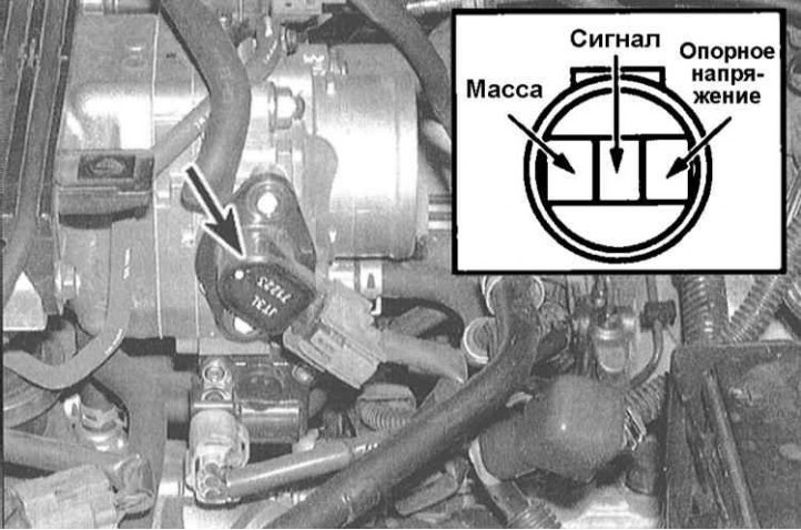
2. Using a voltmeter, measure the reference voltage supplied to the sensor from the PCM. Disconnect the wiring harness from the sensor and connect the voltmeter probes to the REF terminals (+) and GND (-) connector. With the ignition on (do not start the engine) the device should register about 5.0 V. The absence of voltage indicates an open in the PCM circuit or failure of the module itself.
3. Now check the sensor signal voltage. With the engine off and throttle wide open, connect a voltmeter between the SIG terminals (+) and GND (-) TPS connector.
Note. To connect the voltmeter to the back side of the connector terminals, it is convenient to use an unbent metal paper clip. Gradually open the shutter, observing the readings of the voltmeter. When the throttle is closed, the signal voltage value should be 0.5÷1.5 V and, gradually, increasing, reach a value of 4.5 V when the damper is fully opened, otherwise replace the TPS.
Replacement
The TPS is permanently attached to the throttle body and can only be replaced as part of the entire assembly (see chapter Power and exhaust systems).