
(Types: Honda Lock and Murakumi)
1. Remove the power mirror from the door and disconnect the 8K connector.
2. Remove the mirror base cover from the mirror base.
3. Remove the two screws and cut the wires, then write down the pin locations and wire colors.
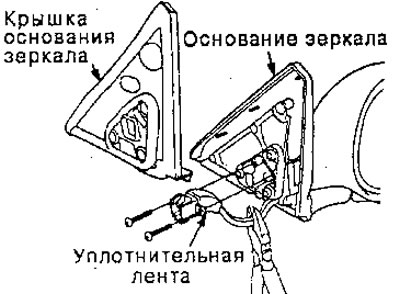
4. Remove the three mounting screws and separate the mirror base from the mirror housing.
5. Insert a flat-head screwdriver into the slot between the mirror housing and the mirror holder, then pull out the mirror.
Note: Be careful not to damage the mirror housing.
6. Honda Lock Type:
Remove the four screws and separate the mirror frame from the mirror housing. Then remove
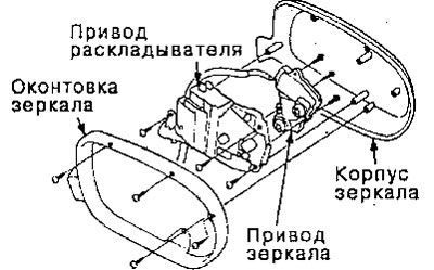
7. Murakumi:
Remove the three screws that secure the drive to the frame, then remove the drive.
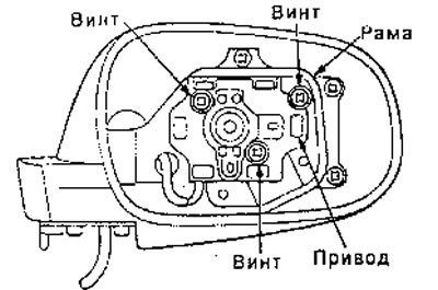
8. Feed the new drive wiring through the shaft hole.
9. Mount the drive and mirror frame (Honda Lock), having screwed in the screws.
10. Attach the drive to the mirror base by pressing it into place with your hands.
11. Assemble the mirror base and mirror housing by tightening the screws.
12. Insert the contacts into the connector in their original position (recorded during the execution of item 3), as shown below.
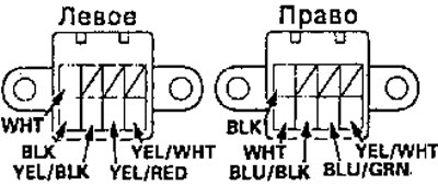
13. Wrap the intersection of the connector and the wiring with sealing tape.
14. Install the connector into the mirror base.
(Donnelly type)
1. Remove the power mirror from the door and disconnect the 8K connector.
2. Remove the mirror base cover from the mirror housing,
3. Remove the mirror holder from the mirror housing. Carefully pull it out with your hands.
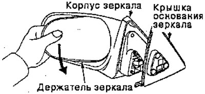
4. Remove the three screws from the drive and two screws from the base of the assembly bracket.
5. Remove the bracket from the housing
6. Remove two screws, cut the wiring and remove the drive.
7. Record the location of the contacts and the color of the wires.
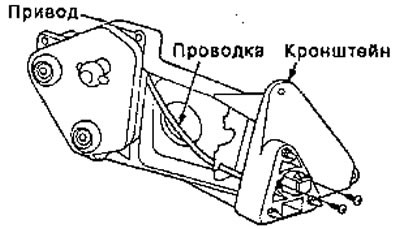
8. Feed the new drive wiring through the hole in the bracket.
Note: Make sure to route the wire under the bracket clip.
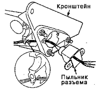
9. Place the connector boot onto the wiring.
10. Insert the contacts into the connector in their original position (which was written in paragraph 7), as shown below.
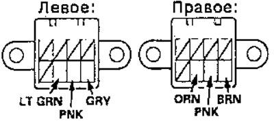
11. Wrap the sealing tape around the intersection of the connector boot and the wiring.
12. Assemble in the reverse order of disassembly.