
2. Loosen the screws securing the handle and remove it.
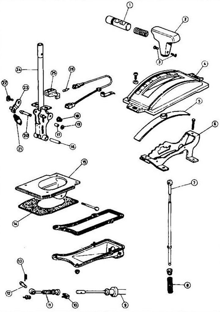
Fig. 6.2 Assembly of the shift lever: 1 - button; 2 - handle; 3 - screw; 4 - lever position indicator; 5 - lever cover; 6 - lever mounting bracket; 7 - lock rod; 8 - traction spring; 9 - cable; 10 - latch; 11 - cable length regulator; 12 - finger; 13 - latch; 14 - gasket; 15 - lever bracket; 15 - spacer; 16 - spacer; 17 - spacer; 18 - nut; 19 - stopper; 20 - castle; 21 - spring; 22 -bolt; 23 - stopper; 24 - control lever; 25 - lever position indicator; 26 - light bulb.
3. Remove the gear shift indicator panel.
4. Remove the connector from the neutral position switch, gear shift indicator and, if equipped, the shaft lock solenoid.
5. Disconnect the cable from the lever (see Section 4).
6. Loosen the bolts securing the lever assembly and remove it.
7. Installation is carried out in the reverse order of removal. Do not forget to adjust the cable afterwards (see Section 4).