
Contents: Examination ⇊ Replacement ⇊
Examination
1. Connect the diagnostic tool to the DLC connector.
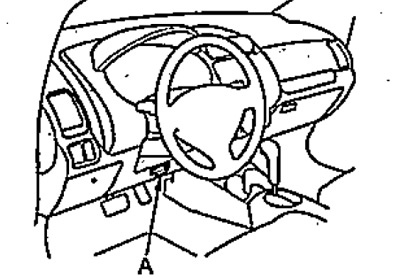
2. Select "Shift Solenoid A, B, C and D" from the "Miscellaneous" menu of the device.
3. Using a diagnostic device, check the operation of the electromagnetic valves; clicks should be heard.
If clicks are not heard, check the resistance of the electromagnetic valves.
4. Checking the resistance of electromagnetic valves.
a) Pull out the parking brake lever, place chocks under the rear wheels and jack up the front of the vehicle.
b) Remove the mudguards.
c) Disconnect the solenoid valve connector.
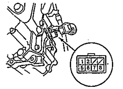
t) Measure the resistance between ground and the following connector terminals one by one:
- terminal "1" - electromagnetic valve "C";
- terminal "2" - electromagnetic valve "B";
- terminal "3" - z/m valve "A";
- terminal "4" - electromagnetic valve "D".
If the resistance is normal, check the functionality of each solenoid valve (see item "S"). If the resistance is not normal, replace the faulty solenoid valve.
- Resistance - 12 - 25 Ohm
5. Check the functionality of each solenoid valve by connecting each of the terminals specified in point "4" to the positive terminal of the battery in turn.
When the solenoid valve is operating, clicks should be heard. If clicks are not heard, replace the solenoid valve.
6. If necessary, remove the solenoid valves (see the "Replacement" subsection) and check the resistance between the solenoid valve terminal and ground.
- Resistance - 12 - 25 Ohm
If the resistance of the solenoid valve is normal, replace the wires with the connector.
If the resistance of the solenoid valve is not within the norm, replace the valve.
7. Install the fender liners.
8. Lower the vehicle.
Replacement
1. Pull out the parking brake lever, place chocks under the rear wheels and jack up the front of the car.
2. Remove the mudguards.
3. Disconnect the solenoid valve connector.
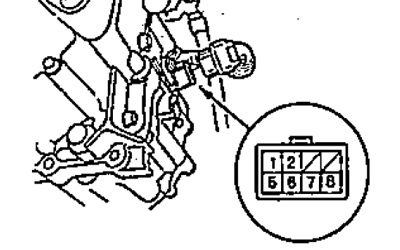
4. Unscrew the drain plug (A), remove the gasket (B) and drain the automatic transmission fluid.
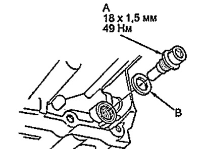
5. Install a new gasket and tighten the drain plug.
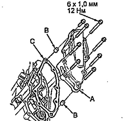
6. Loosen the bolts and remove the solenoid valve cover (A), pins (B) and gasket (C).
7. Disconnect the connectors from the shift solenoid valves.
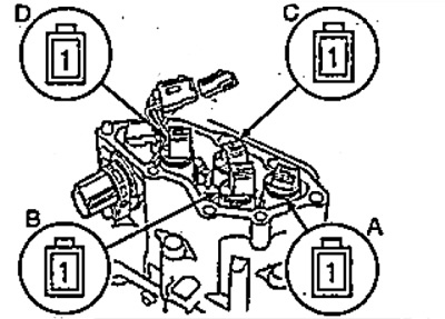
A - electromagnetic valve "A",
B - solenoid valve "B",
C - electromagnetic valve "C",
D - electromagnetic valve "D".
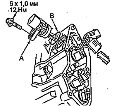
8. If it is necessary to replace the wires, unscrew the bolt and remove the connector (A) with the wires. Remove the O-ring (B).
9. If it is necessary to replace the solenoid valve, unscrew the bolt and remove the solenoid valve. Remove the O-rings (E).
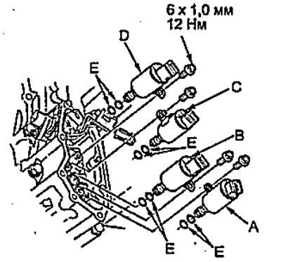
A - electromagnetic valve "A",
B - electromagnetic valve "B",
C - electromagnetic valve "C",
D - electromagnetic valve "D",
E - O-ring seal.
10. Install the O-rings (2 pieces) on the re-installed solenoid valve.
Note: New solenoid valves already have O-rings installed.
11. Install solenoid valve "D" (black connector) and solenoid valve "C" (brown connector) and tighten the bolts.
- Tightening torque - 12 Nm
12. Install solenoid valve "B" (black connector), then solenoid valve "A" (brown connector) and tighten the bolts.
- Tightening torque - 12 Nm
13. Connect the connectors to the solenoid valves according to the connector colors.
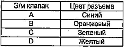
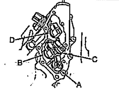
A - electromagnetic valve "A",
B - electromagnetic valve "B",
C - electromagnetic valve "C",
D - electromagnetic valve "D".
14. Install the pins and gasket onto the solenoid valve cover. Install the cover and tighten the bolts.
- Tightening torque - 12 Nm
15. Make sure that there is no rust, dirt or oil on the solenoid valve connector and connect the connector.
16. Fill the gearbox with oil (see chapter "Maintenance and general checking and adjustment procedures").
17. Install the fender liners.
(The original can be found on the resource: Hondabook.ru)