
Contents: Relays and fuses ⇊ Table. Location of fuses (mounting…⇊ Table. Location of fuses (mounting…⇊ Checking the relay ⇊
Relays and fuses
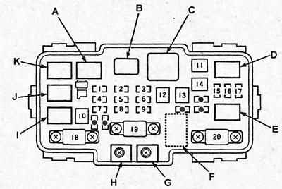
Location of relays and fuses (mounting block in the engine compartment). A - air conditioner compressor electromagnetic clutch relay, B - rear window heater relay, C - heater fan relay, D - headlight relay No.1, E - headlight relay No.2, F - supply voltage monitoring system unit, G - from generator terminal "B" (engine wiring harness), H - from the positive terminal of the battery (engine wiring harness), I - condenser fan relay, J - horn relay, K - cooling system fan relay.
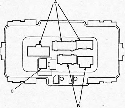
Location of connectors (mounting block in the engine compartment). A - wiring harness in the engine compartment, B - wiring harness in the engine compartment, C - to the voltage control system unit (wiring harness in the engine compartment).
Table. Location of fuses (mounting block in the engine compartment).
| № | Current, A | Wire color | Purpose |
| 1 | 20 | BI/Y | Condenser Fan Motor |
| BI/R | Air conditioning compressor electromagnetic clutch relay | ||
| 2 | 15 | W/G | Side light relay, connector for connecting additional equipment (V), side lights, license plate light, switch light, ashtray light, air conditioning and heating control panel light, instrument cluster light, radio light (models without navigation system), multivision system block illumination (models with navigation system), navigation system control unit |
| 3 | 7,5 | W/BI | Luggage compartment light, ignition switch light, interior light, local light |
| 4 | 20 | BI/B | Electric motor of the cooling system fan |
| 5 | 10 | W/B | Direction indicator relay |
| 6 | 15 | W/B | Main relay of injection system No.1, powertrain control unit, idle speed control system valve, TDC sensor, crankshaft position sensor, injectors, main relay of injection system No.2, immobilizer receiver 3 |
| 7 | 15 | W/G | Brake lights, additional brake light, powertrain control unit, pressure modulator and ABS control unit |
| BI/R | Sound signal | ||
| - | Horn relay | ||
| 8 | 20 | W/G | Pressure modulator and ABS control unit |
| 9 | 10 | W/R | Diagnostic connector, instrument cluster, central locking remote control unit, navigation system control unit, Multivision system unit (models with navigation system), radio tape recorder (models without navigation system), multiplex control unit, immobilizer receiver*3 |
| 10 | 40 | W/R | Pressure modulator and ABS control unit |
| 11 | 30 | BI*1 | Rear window defroster |
| BI/Y*2 | Rear window defroster, interference suppression filter | ||
| 12 | 40 | BI/W | Heater Fan Motor |
| 13 | 40 | W/B | Fuses #7, #22, #23, #24 and #25 (mounting block in the cabin) |
| 14 | 40 | W/R | Fuse #2 (mounting block in the cabin), connector for connecting additional equipment (U) |
| 15 | 15 20*3 | R/Y | Left headlight bulb (models without gas discharge lamps), gas discharge lamp of the left headlight (models with gas discharge lamps), high beam indicator |
| 16 | 20 | W | Multiplex Control Unit |
| 17 | 15 20*3 | R | Right headlight bulb (models without gas discharge lamps), gas discharge lamp of the right headlight (models with gas discharge lamps) |
| 18 | 60 | W/BI | Electric Power Steering Control Unit |
| 19 | 80 | - | Battery |
| 20 | 40 | W | Ignition switch |
- *1 - sedan,
- *2 - hatchback
- *3 - models produced since 9/2003.
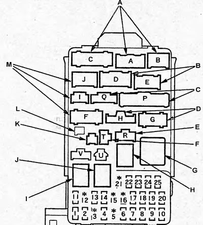
Location of relays, connectors and fuses (mounting block in the cabin). A - Combination switch wiring harness, B - Powertrain control unit wiring harness, C - Floor wiring harness, D - Engine compartment wiring harness, E - Powertrain control unit wiring harness, F - Multiplex control unit diagnostic connector, G - Direction indicator flasher relay, H - Power window relay, I - Starter relay, J - Sidelight relay, K - Code erase connector (wiring harness in the floor), L - not used, M - wiring harness in the engine compartment.
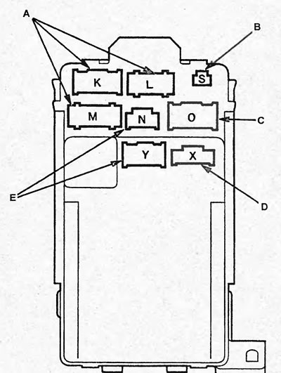
Location of connectors (mounting block in the cabin). A - Instrument cluster wire harness, B - Combination switch wire harness, C - Instrument cluster wire harness, D - Combination switch wire harness, E - Instrument cluster wire harness.
Table. Location of fuses (mounting block in the cabin).
| № | Current, A | Wire color | Purpose |
| 1 | 15 | B/W | Ignition coils |
| 2 | 20 | W/R | Air-fuel ratio sensor (models with D15B SOHC VTEC (lean burn) engine), powertrain control unit (models with D15B SOHC VTEC (lean burn) engine) |
| 3* | 15 | BI/R | Fog lights (sedan) |
| 4 | 10 | IN | Generator, vehicle speed sensor (models with manual or automatic transmission), front oxygen sensor (except models with D15B SOHC VTEC (lean burn) engine), Rear oxygen sensor, Evaporative emission control solenoid valve, Power supply voltage monitoring unit, Air-fuel ratio sensor relay (models with D15B SOHC VTEC (lean burn) engine) |
| 5 | - | - | Not in use |
| 6 | 7,5 | Y/G | Sunroof opening relay, sunroof closing relay, window lifter control unit, sunroof electric drive control unit (hatchback) |
| - | Window lifter relay | ||
| 7 | 20 | G | Hatch drive electric motor |
| 8 | 7,5 | Y/R | Navigation system control unit, Multivision system unit (models with navigation system), radio tape recorder (models without navigation system). |
| - | Multiplex control unit (models with automatic transmission or continuously variable transmission (CVT)), connector for connecting additional equipment (V) | ||
| 9 | 10 | G | Rear window wiper motor, rear window washer pump, front passenger position detection system unit (models with side airbags) |
| 10 | 7,5 | Y | Reversing light relay (models with automatic transmission or continuously variable transmission (CVT)), reversing lights, selector lock solenoid valve (models with automatic transmission or continuously variable transmission (CVT)), instrument cluster, remote central locking system unit, electric power steering control unit |
| - | Multiplex Control Unit | ||
| 11 | 7,5 | IN | Pressure modulator and ABS control unit |
| 12 | - | - | Not used |
| 13 | 10 | P | Passive safety system control unit |
| 14 | 10 | B/Y | Rear window defroster relay, heater fan relay, cooling fan relay, condenser fan relay, air conditioner compressor electromagnetic clutch relay, mirror drive motors, air intake switch actuator, air conditioner and heater control unit |
| - | Connector for connecting additional equipment (V) | ||
| 15 | - | - | Not used |
| 16 | - | - | Not used |
| 17 | 15 | B/Y | Passive safety system control unit |
| Y | Fuel pump, powertrain control unit | ||
| 18 | 15 | Y/G | Cigarette lighter |
| 19 | 7,5 | Y/B | Direction indicator relay |
| 20 | 20 | G/B | Windshield wiper motor, windshield washer electric pump |
| - | Multiplex Control Unit | ||
| 21 | - | - | Not used |
| 22 | 20 | G/B | Electric window lifter front passenger door |
| 23 | 20 | G/W | Electric window lifter driver's door |
| 24 | 20 | Y/R | Electric window lifter rear left door |
| 25 | 20 | Y/BI | Electric window lifter rear right door |
* - models produced since 9/2003.
Checking the relay
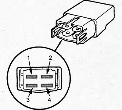
Type 1
1. Remove the relay.
2. Make sure there is no conductivity between terminals "1" and "2".
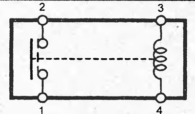
Relay type 1:
- side light relay;
- horn relay;
- fog light relay;
- reverse Light Relay;
- window lift relay;
- headlight relay #1;
- headlight relay #2;
- cooling fan relay;
- condenser fan relay;
- air conditioner compressor electromagnetic clutch relay;
- air-fuel ratio sensor relay (models with D15B SOHC VTEC (lean burn) engine);
- main relay of injection system no.1;
- main relay of injection system No.2.
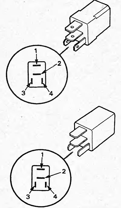
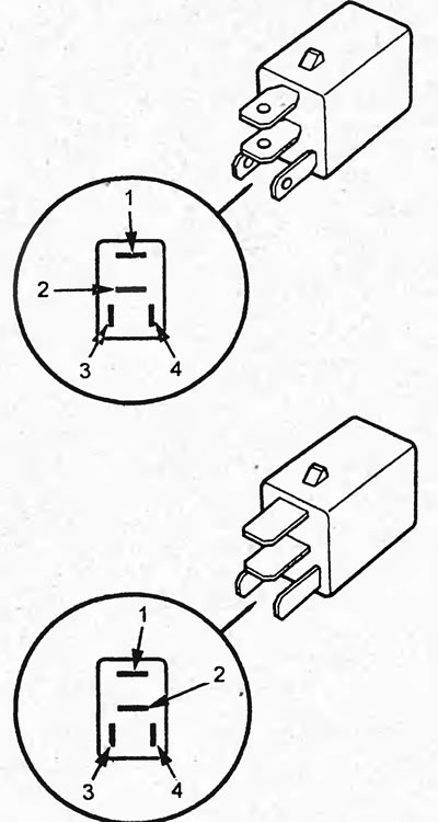
3. Make sure there is conductivity between terminals "3" and "4".
4. Connect the battery to terminals "3" and "4", make sure there is conductivity between terminals "1" and "2".
Type 2
1. Remove the relay.
2. Make sure there is no conductivity between terminals "1" and "3".
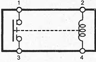
Relay type 2:
- rear window defroster relay;
- heater fan relay;
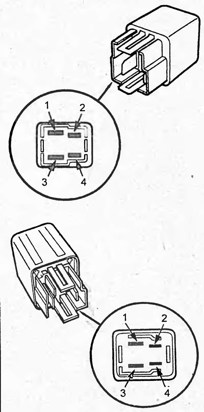
3. Make sure there is conductivity between terminals "2" and "4".
4. Connect the battery to terminals "2" and "4", make sure there is conductivity between terminals "1" and "3".
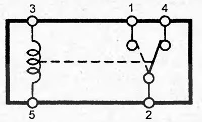
Type 3
1. Remove the relay.
2. Make sure there is conductivity between terminals "3" and "5".
3. Make sure there is conductivity between terminals "2" and "4" and there is no conductivity between terminals "2" and "1".
Relay type 2:
- sunroof opening relay;
- hatch closing relay.
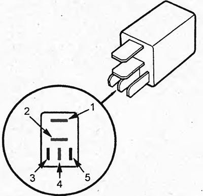
4. Connect the battery to terminals "3" and "5", make sure there is conductivity between terminals "2" and "1" and there is no conductivity between terminals "2" and "4".