
Control
1. The switch is located at the top of the brake pedal.
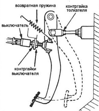
Pic. 15.1 Typical installation diagram of the brake light switch
2. Disconnect the switch connector.
3. Check up conductivity between contacts by means of an ohmmeter. There should be no continuity when the switch plunger is pressed; when it is not pressed, there is continuity. If the switch does not function as described, replace it.
Replacement
4. Disconnect the electrical connector, if not already disconnected.
5. Loosen the switch locknut (see fig. 15.1) and remove it from the bracket.
6. Installation is carried out in the reverse order of removal
Adjustment
7. Loosen the switch locknut on the switch side and move it until the plunger is fully depressed by the pedal pusher.
8. Move the switch back half a turn and tighten the locknut.
9. Check the operation of the switch: when you press the pedal, the brake lamp should be on, when the pedal is released, no.