
- Use only genuine Honda weights for aluminum rims. Non-original weights can cause corrosion and damage to aluminum rims.
- Remove the center cap from the inside of the aluminum rims after removing the wheels.
- Before installing the brake disc, clean the contact surfaces on the front wheel hub and on the brake disc.
- Before installing the wheel, clean the contact surfaces on the brake disc and on the wheel.
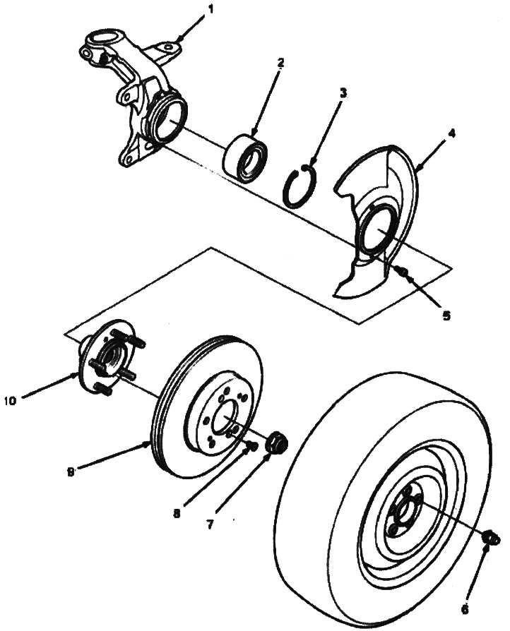
1. KNUCKLE
2. WHEEL BEARING. Replace
3. RING CLAMP
4. MUD SHIELD
5. SCREW, 5x0.8 mm, 5.9 Nm (0.6 kgf/m)
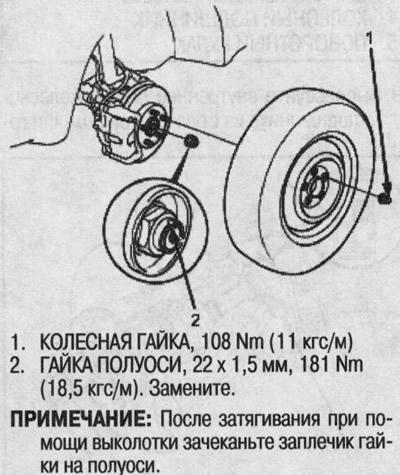
6. WHEEL NUT, 12x1.5 mm, 108 Nm (11.0 kgf/m)
7. HALF NUT, 22x1.5 mm, 181 Nm (18.5 kgf/m). Replace.
Apply engine oil to the seating surface of the nut before tightening the axle nut.
After tightening with a drift, caulk the shoulder of the nut on the axle shaft.
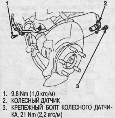
8. FIXING SCREW 6 mm BRAKE DISC, 9.8 Nm (1.0 kgf/m)
9. BRAKE DISC. Check for wear and rust.
10. FRONT WHEEL HUB. Check for damage and cracks.
1. Slightly loosen the wheel nuts.
2. Raise the front of the vehicle and secure it to the safety stands at the correct points.
3. Loosen the wheel nuts and remove the wheel.
4. Bend the locking tab on the axle shaft nut, then unscrew the nut.
5. Turn off fixing bolts of a brake hose.
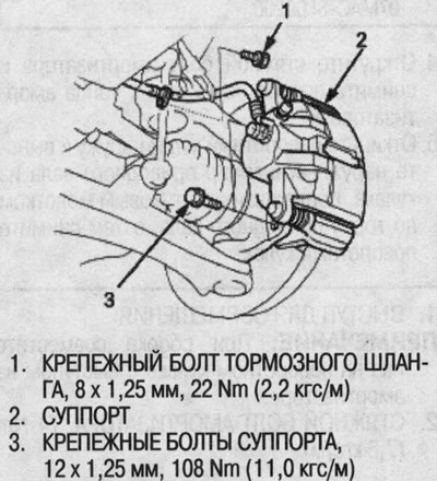
6. Remove the caliper mounting bolts and hang the caliper assembly from the side. To prevent accidental damage to the caliper assembly or brake hose, tie the caliper to the bottom with a wire.
7. Loosen the fixing screws of the 6mm brake disc.
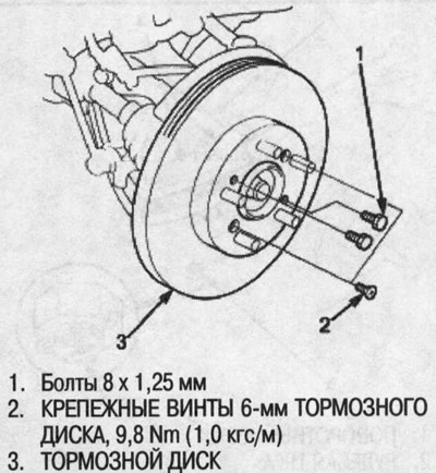
8. Screw two 8x1.25mm bolts into the disc to separate it from the hub. To avoid excessive disc warping, screw in the bolts two turns at a time.
9. Remove the brake disc from the steering knuckle.
10. Check the front wheel hub for damage and cracks.
11. Remove the wheel sensor from the steering knuckle. Do not disconnect the wheel sensor connector (on models with ABS).
12. Wipe dirt or grease from the ball joint.
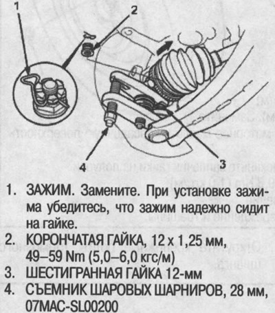
13. Remove the cotter pin from the lever and unscrew the nut.
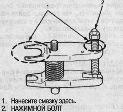
14. Apply grease to the special tool in the indicated areas. This will make it easier to install the caliper and prevent damage to the jack bolt threads.
15. Loosen the 12mm nut on the tie rod end ball joint. Make sure the nut is flush with the end of the ball joint pin to avoid damaging the threaded tie rod end.

16. Install the special tool as shown. Insert the claws carefully so as not to damage the ball joint boot. Adjust the distance between the grips by turning the pressure bolt. If necessary, apply wetting fluid to loosen the ball joint.
17. With the special tool installed, turn the adjusting bolt and align the grippers parallel to each other. Then tighten the pressure bolt by hand and check again that the jaws are parallel.
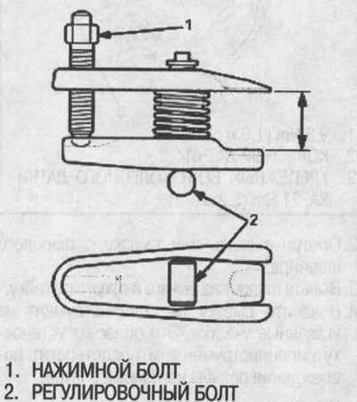
After adjusting the bolt, make sure the head of the bolt is in this position to allow the gripper to turn.
18. Tighten the pressure bolt with a wrench until the ball joint shaft is released from the lever.
Warning! Wear safety goggles. The ball joint can suddenly break off, and dirt and other debris can be thrown into your face.
19. Remove the special tool, then unscrew the nut from the tip of the ball joint and remove the ball joint from the suspension arm. Check the ball joint boot and replace if damaged.
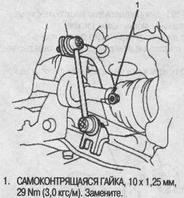
20. Remove the 8mm self-locking nut and separate the stabilizer link from the lower arm.
21. Remove the clip from the lower arm ball joint castle nut and unscrew the nut.
22. Install a 12mm hex nut onto the ball joint. Make sure the hex nut is flush with the end of the ball joint pin, otherwise the threaded portion of the ball joint pin may be damaged by the ball joint remover.
23. Using a special tool (see below) separate the ball joint and steering knuckle. If necessary, apply wetting fluid to loosen the ball joint.
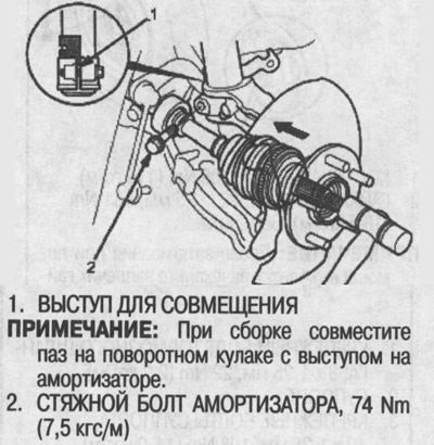
24. Turn off a coupling bolt of the shock-absorber and remove a rotary fist from the end of the shock-absorber.
25. Tilt the steering knuckle out and remove the drive shaft outer joint from the knuckle by tapping the end of the drive shaft with a plastic hammer, then remove the steering knuckle.
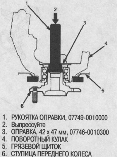
26. Separate the hub from the steering knuckle using a bearing separator and a hydraulic press.
Warning!
- Do not deform the mudguard.
- Hold the hub when separating so that it does not fall.
- In order not to damage the special tool, make sure that the thread is completely screwed in before pressing out.
27. Remove the ring clip and mud shield from the steering knuckle.
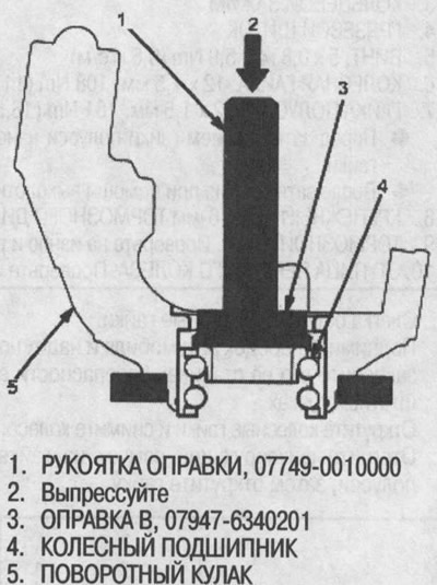
28. Using a special tool, press the wheel bearing out of the steering knuckle.
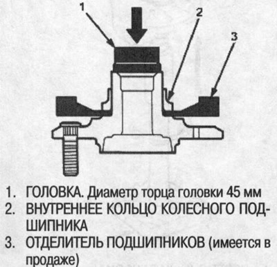
29. Press the wheel bearing inner race out of the hub using a suitable diameter socket and bearing separator.
30. Before assembly, thoroughly wash the steering knuckle and hub in a special solvent.
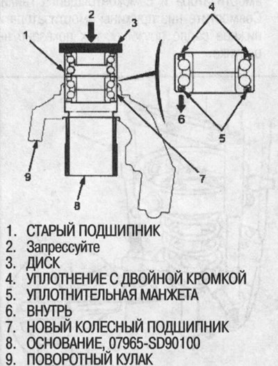
31. Press the new wheel bearing into the steering knuckle using the old bearing, disc, special tool and press. Install the wheel bearing on the steering knuckle with a sealing collar (metallic color) inside. Do not damage the seal sleeve.
32. Securely insert the ring clip into the groove of the steering knuckle.
33. Install the mudguard and tighten the screws.
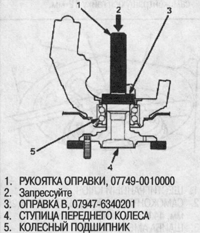
34. Using a special tool, press the hub into the steering knuckle. Do not deform the mudguard.
35. Establish a rotary fist in an order, the return to removal, paying special attention to the following:
- When installing the steering knuckle, do not damage the covers of the ball joints.
- Tighten all fasteners to the required torque.
- Tighten the castle nuts to the lowest tolerance, then tighten just enough to align the slot with the cotter pin hole. Do not do this by loosening the nut.
- After tightening, install new cotter pins on the castle nuts.
- When installing the wheel sensor, avoid twisting the sensor wire.
- Before installing the brake disc, clean the contact surfaces on the front wheel hub and on the brake disc.
- Apply engine oil to the seating surface of the nut before tightening the axle nut. After tightening with a punch, caulk the shoulder of the axle nut on the drive shaft.
- Before installing the wheel, clean the contact surfaces on the brake disc and on the wheel.
- Check the front wheel alignment and adjust if necessary (see above).