
Preliminary check
For proper control and correction of camber/toe-in, perform the following checks.
1. Release the parking brake to avoid measurement error.
2. Make sure the suspension has not been modified.
3. Check tire size and adjust tire pressure as recommended.
4. Check up beating of disks and tires.
5. Check up a condition of spherical hinges of a suspension bracket. Hold the wheel with your hands and rock it up and down and from side to side, checking for play.
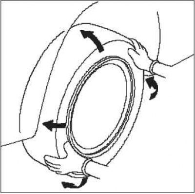
6. Rock the car up and down several times to stabilize the suspension.
Kingpin angle check
1. Raise the front of the vehicle and remove the wheel covers.
Note. Press the cap on the aluminum rim from the inside after removing the rim.
2. Install steering angle gauges under the front wheels, and under the rear wheels - wooden blocks of the same thickness with the steering angle gauges. Lower the car.
Note. Check that the vehicle is in a perfectly level position on the steering angle gauges and wooden blocks.
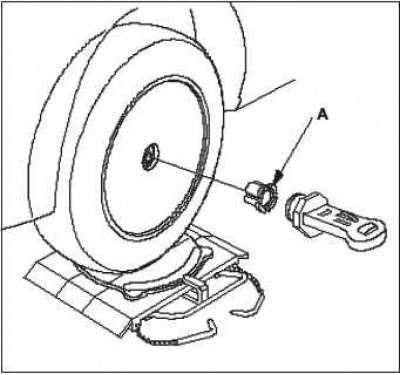
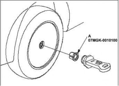
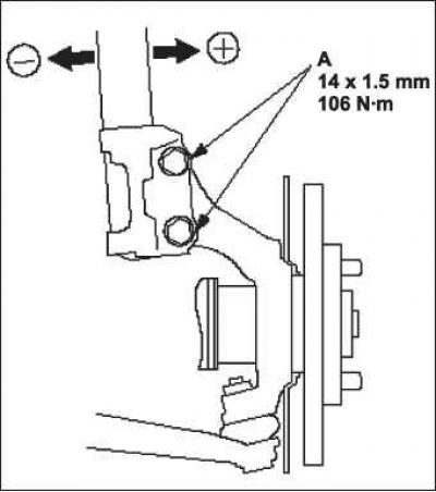
3. Install the toe gauge and kingpin/camber gauge on hub A and depress the brake pedal.
4. Rotate the front wheel 20°outward, then turn the kingpin/camber adjustment screw to set the bubble to 0°.
5. Turn the wheel 20°inward and read the king pin angle value on the vial on the fixture scale. If the kingpin angle is not within the specified tolerance, check the suspension for deformed or damaged components.
Kingpin Angle: 4°14'±30'.
Checking the angle of inclination of the kingpin of the front suspension
1. Set the front wheels to straight ahead.
2. Raise the front of the vehicle and remove the wheel covers.
Note. Press the cap on the aluminum rim from the inside after removing the rim.
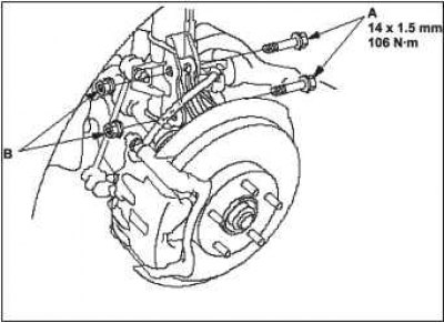
3. Install wheel alignment tool A and kingpin/camber tool on the hub.
4. Look at the bubble on the tool scale for the value of the camber angle. If the camber angle is out of specification, adjust it.
Camber angle of the front wheels.
Max gap between right and left edge: 0°00'±30'0°30'.
Adjusting the angle of inclination of the kingpin of the front suspension
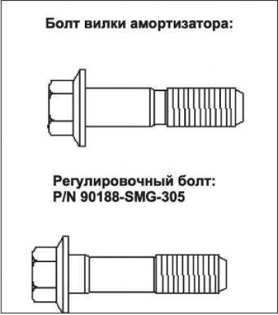
The angle of the front suspension kingpin can be adjusted by replacing one of the shock absorber fork bolts with an adjusting bolt (s) smaller diameter. The difference between the diameter of the adjusting bolt and the diameter of the mounting bolt hole allows a small range of adjustment.
1. Raise the front of the vehicle and place safety stands in the appropriate positions.
2. Remove the front wheels.
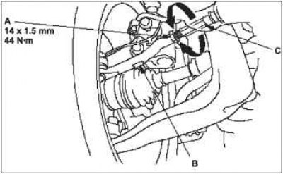
3. Loosen the shock absorber yoke bolts A and adjust the camber angle by moving the bottom of the shock absorber within the free play range of the shock mounting bolt.
4. Tighten the shock absorber mounting bolts to the recommended torque. Make sure the shock absorber mounting bolts are securely tightened.
5. Reinstall the front wheels. Lower the front of the car to the ground, and rock the front of the car up and down a few times to stabilize the suspension.
6. Measure the camber angle.
If the measurement results are correct, check the wheel alignment.
If the measurement results are not correct, go to step 7.
7. Raise the front of the vehicle and place safety props in appropriate locations.
8. Remove the front wheels.
9. Replace the shock absorber fork bolts with adjusting bolts A, and adjust the camber angle.
Note. The camber angle can be adjusted up to±20' by replacing both shock absorber fork bolts with adjusting bolts.
If the measurement results are below±50' (midrange), replace one shock absorber fork bolt with an adjusting bolt.
If the measurement results are below±50' (midrange), replace one shock absorber fork bolt with an adjusting bolt.
The camber angle can be adjusted up to 1°, (midrange) by replacing both (upper and lower) shock absorber fork bolts with adjusting bolts. However, the maximum gap between the right and left edges is 2°.
When installing, use new nuts B.
10. Tighten the adjusting bolts to the recommended torque.
11. Reinstall the front wheels. Lower the front of the car to the ground, and rock the front of the car a few times to stabilize the suspension.
12. Measure the camber angle. If the camber angle is out of specification, repeat steps 6 to 11 to re-adjust the camber angle. If the camber measurements are correct, measure the wheel alignment and adjust if necessary.
Checking the camber angle of the rear wheels
1. Raise the rear of the vehicle and remove the wheel covers.
Note. Press the cap on the aluminum rim from the inside after removing the rim.
2. Install wheel toe gauge A and kingpin/camber gauge onto the hub.
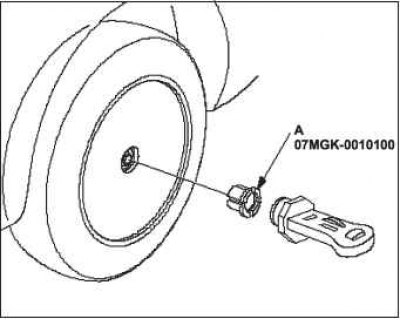
3. Look at the bubble on the tool scale for the value of the camber angle. If the camber angle is not within the specified tolerance, check the suspension for deformed or damaged components.
Rear camber: -1°00'±30'.
Checking and adjusting the toe-in of the front wheels
1. Set the steering wheel to the center position.
2. Check the wheel alignment. If it is not included in the normalized tolerance, go to step 3.
Convergence of forward wheels: 0±2 mm.
3. Loosen lock nut A while holding tie rod end B with a wrench.
Note. Hold the tip of the rail with the wrench, preventing it from turning.
4. Turn tie rods C until correct toe is set.
Note. Adjustment of the right and left wheels should be carried out simultaneously, turning in opposite directions by the same angle, so that with the correct convergence, the steering wheel remains in the center position.
5. After adjusting the toe, tighten the locknut while holding the tie rod. Verify that the convergence value has not changed.
Checking the convergence of the rear wheels
1. Release the parking brake lever.
2. Check the wheel alignment. If the camber angle is out of specification, check the suspension for deformed or damaged components.
Convergence of back wheels: 4±2 mm.
Checking the ratio of the angles of rotation of the wheels
1. Raise the car and place wheel angle gauges under the front wheels, and wooden blocks of the same thickness with the steering angle gauges under the rear wheels. Lower the car.
Note. Check that the vehicle is in a perfectly level position on the steering angle gauges and wooden blocks.
2. With the brake pedal depressed, turn the steering wheel all the way to the left and right and check the wheel angles. If the steering angles are not within the allowed limits or there is a difference in the limiting steering angles of the right and left inner wheels, go to step 3.
Angle of rotation
Internal
16" diameter wheel: 38°32'±2°.
17" diameter wheel: 36°32'±2°.
Outdoor (example)
16" wheel: 32°31'.
17" wheel: 31°16'.
3. Check up a convergence of wheels. If the wheel toe-in is normal and the steering angle difference is out of range, check the suspension for deformed or damaged components.