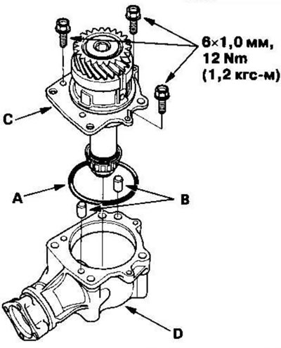
Selection of thrust washer 35 mm
1. Select a 35mm thrust washer when replacing the transfer case driven gear shaft or the tapered roller bearing on the transfer case driven gear shaft. Calculate the thickness of the 35mm thrust washer using the following formula:
Formula: A/100-B/100+C=X
A: The number on the existing shaft of the transfer case driven gear.
Q: Number on the replacement shaft of the transfer case driven gear.
C: The thickness of the existing thrust washer is 35 mm.
X: Required thickness for replacement thrust washer 35mm.
Note: The number on the transfer case driven gear shaft is indicated in 1/100 mm.
Example:
A: existing shaft of the driven gear of the transfer case
B: Replaceable shaft of the transfer case driven gear
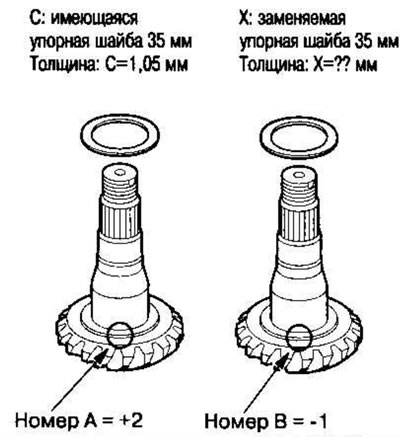
X=A/100-B/100+C=2/100-(-1/100)+1.05=1.08
If replacing the tapered roller bearing on the transfer case driven gear shaft, select a 35 mm thrust washer.
Measure the thickness of the bearing being replaced and the existing bearing. Adjust the thickness of the existing 35 mm thrust washer to account for the difference in bearing thickness and select a replacement 35 mm thrust washer. Adjust the transfer case gear clearance using only one 35 mm thrust washer.
Thrust washer, 35 mm
| Catalogue number | Thickness | |
| A | 41361-PS3-000 | 0.72 mm |
| IN | 41362-PS3-000 | 0.75 mm |
| WITH | 41363-PS3-000 | 0.78 mm |
| D | 41364-PS3-000 | 0.81 mm |
| E | 41365-PS3-000 | 0.84 mm |
| F | 41366-PS3-000 | 0.87 mm |
| G | 41367-PS3-000 | 0.90 mm |
| N | 41368-PS3-000 | 0.93 mm |
| I | 41369-PS3-000 | 0.96 mm |
| J | 41370-PS3-000 | 0.99 mm |
| TO | 41371-PS3-000 | 1.02 mm |
| L | 41372-PS3-000 | 1.05 mm |
| M | 41373-PS3-000 | 1.08 mm |
| N | 41374-PS3-000 | 1.11 mm |
Checking the clearance in the transfer case gears and the contact pattern of the teeth in the transfer case gears
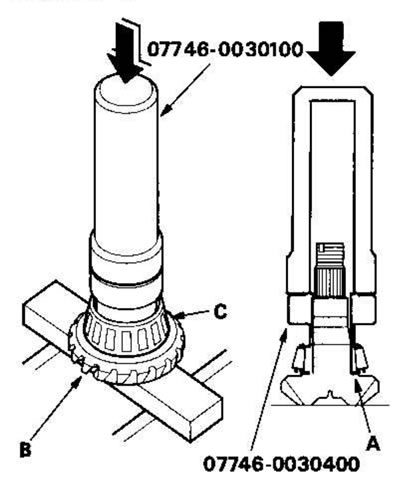
2. Install the 35mm thrust washer (A) onto the transfer case driven gear shaft (B), then press in the tapered roller bearing (C) using the special tool and a press.
3. Press the bearing outer race, then the tapered roller bearing (A) into the transfer case housing from the connecting flange side.
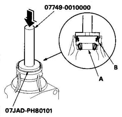
4. Press the new oil seal (B) into the transfer case housing using a special tool.
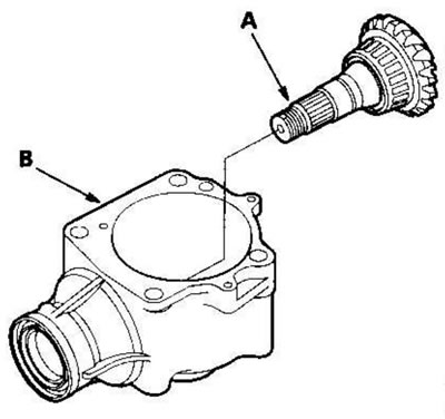
5. Install the transfer case driven gear (A) into the transfer case housing (B). Do not install the transfer case spacer sleeve onto the transfer case driven gear shaft at this stage.
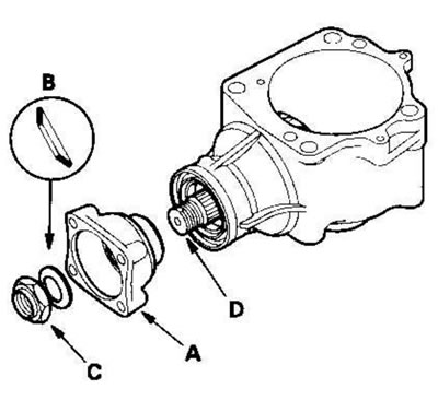
6. Install the coupling flange (A), conical spring washer (B) and locknut (C) onto the driven gear (D) of the transfer case. Do not install the O-ring and protective ring onto the transfer case pinion shaft at this stage.
7. Secure the transfer case housing (A) in a vice (B) with soft jaws, then install the special tool on the connecting flange.
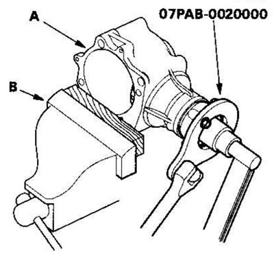
Note: To avoid damaging the transfer case housing, always secure it in a soft jawed vice or use a spacer between the vice and the transfer case.
8. While tightening the lock nut, measure the starting torque so that it is within 1.08-1.47 Nm (11.0-15.0 kgf·cm)
Note:
- Before tightening the locknut, apply transmission fluid to the locknut and shaft threads.
- Do not taper the locknut at this stage.
Starting torque: 1.08-1.47 Nm (11.0-15.0 kgf·cm)
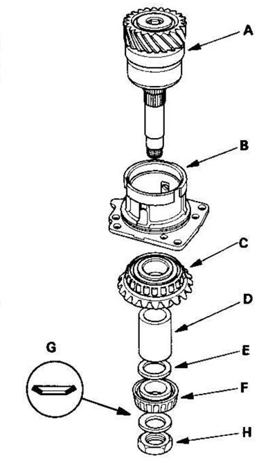
9. Install the transfer case shaft assembly (A) into the transfer case holder (B), then install the transfer case pinion gear (C), transfer case shaft spacer (D), 25 mm thrust washer (E), tapered roller bearing (F), tapered spring washer (G) and locknut (H) onto the transfer case shaft.
Note:
- Before tightening the locknut, apply transmission fluid to the locknut and shaft threads.
- Do not taper the locknut at this stage.
10. Secure the transfer case shaft (A) with a 14 mm wrench (B) in a vice, then tighten the lock nut.
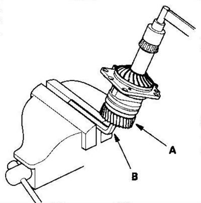
Note: Do not taper the locknut at this stage.
Tightening torque: 118 Nm (12.0 kgf·m)
11. Apply a thin layer of red lead evenly to both sides of the transfer case drive gear teeth.
12. Install the dowel pin (A) and transfer case holder assembly (B) into the transfer case housing (C).
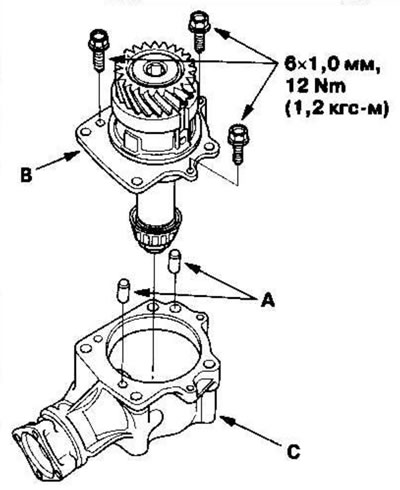
Note: Temporarily install the transfer case bracket assembly without the O-ring.
13. Rotate the coupling flange several times to seat the tapered roller bearing.
14. Install the indicator head (A) on the coupling flange (B), then measure the clearance in the transfer case gears.
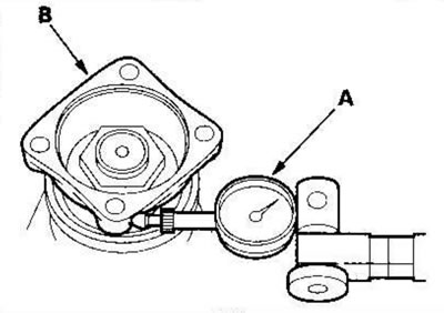
Standard: 0.06-0.16mm
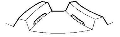
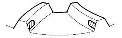
15. Check the contact pattern of the teeth in the transfer case gears.
Correct location of the contact patch on the teeth
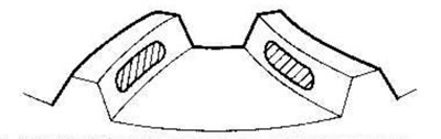
Incorrect contact patch placement on the teeth
At the tip of the tooth
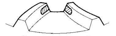
Displaced towards the tooth pedicle
At the heel of the tooth
From the end
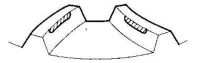
16. If the contact patch on the transfer case gear teeth is not positioned correctly, adjust it using a 35 mm or 25 mm thrust washer. If the contact patch is OK, proceed to step 1. 17.
Note:
- For the procedure for selecting a 35 mm thrust washer, see above.
- To adjust the contact patch on the transfer case gear teeth, use no more than one 35 mm thrust washer.
- See below for the procedure for selecting a 25mm thrust washer.
- To adjust the contact patch on the transfer case gear teeth, use no more than one 25 mm thrust washer.
Contact at the tip of the tooth
To move the transfer case driven gear shaft toward the pinion gear, use a thicker 35 mm thrust washer. Since this movement changes the transfer case gear backlash, adjust it by moving the pinion gear away from the driven gear shaft as follows:
- Increase the thickness of the thrust washer to 25mm.
- Reduce the 76mm thrust washer thickness by the amount of the 25mm thrust washer thickness increase.
Contact displaced towards the tooth leg
To move the pinion gear toward the transfer case driven gear shaft, use a thinner thrust washer. The contact patch, shifted towards the tooth leg, must be adjusted within the lateral clearance between the teeth of the transfer case gears. If the clearance exceeds the specified limits, make adjustments as described for the heel contact.
Contact at the heel of the tooth
To move the transfer case driven gear shaft away from the pinion gear, use a thinner 35 mm thrust washer. Since this movement changes the transfer case gear backlash, adjust it by moving the pinion gear toward the driven gear shaft as follows:
- Reduce the thickness of the thrust washer to 25 mm.
- Increase the 68mm thrust washer thickness by the amount of the 25mm thrust washer thickness reduction.
End contact
To move the pinion gear away from the transfer case driven gear shaft, use a thicker thrust washer. The end contact must be adjusted within the lateral clearance between the teeth of the transfer case gears. If the clearance exceeds the specified limits, make adjustments as described for the toe contact.
Thrust washer, 25 mm
| Puck number | Catalogue number | Thickness |
| 1.70 | 29411-P1C-000 | 1,70 |
| 1.73 | 29412-P1C-000 | 1,73 |
| 1.76 | 29413-P1 C-000 | 1,76 |
| 1.79 | 29414-P1 C-000 | 1,79 |
| 1.82 | 29415-P1 C-000 | 1,82 |
| 1.85 | 29416-P1 C-000 | 1,85 |
| 1.88 | 29417-P1 C-000 | 1,88 |
| 1.91 | 29418-P1 C-000 | 1,91 |
| 1.94 | 29419-P1 C-000 | 1,94 |
| 1.97 | 29420-P1C-000 | 1,97 |
| 2.00 | 29421-P1C-000 | 2,00 |
| 2.03 | 29422-P1C-000 | 2,03 |
| 2.06 | 29423-P1C-000 | 2,06 |
| 2.09 | 29424-P1C-000 | 2,09 |
| 2.12 | 29425-P1C-000 | 2,12 |
| 2.15 | 29426-P1C-000 | 2,15 |
| 2.18 | 29427-P1 C-000 | 2,18 |
| 2.21 | 29428-P1 C-000 | 2,21 |
| 2.24 | 29429-P1 C-000 | 2,24 |
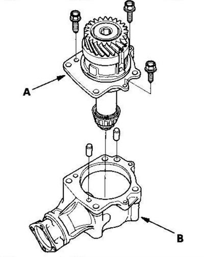
17. Remove the transfer case holder assembly (A) from the transfer case housing (B).
18. Secure the transfer case housing (A) in a vice (B) with soft jaws.
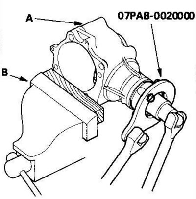
Note: To avoid damaging the transfer case housing, always secure it in a soft jawed vice or use a spacer between the vice and the transfer case.
19. Install the special tool on the connecting flange, then unscrew the lock nut.
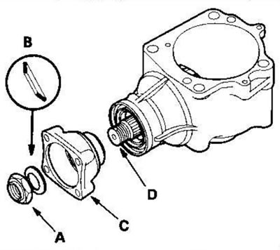
20. Loosen the lock nut (A), remove the conical spring washer (B) and the coupling flange (C) from the transfer case driven gear (D).
21. Remove the transfer case driven gear (A) from the transfer case housing.
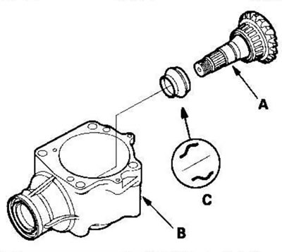
22. Install a new spacer sleeve (C) onto the transfer case driven gear (A), then install them into the transfer case housing (B).
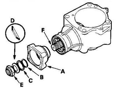
23. Install the coupling flange (A), O-ring (B), protective ring (C), conical spring washer (D) and locknut (E) onto the transfer case driven gear (F).
Note:
- Before tightening the locknut, apply transmission fluid to the locknut threads, O-ring, and transfer case shaft.
- Install the conical spring washer in the direction shown.
24. Secure the transfer case housing (A) in a vice (B) with soft jaws.
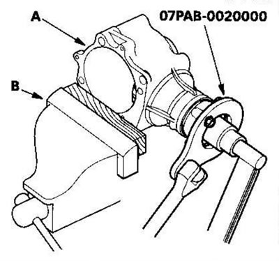
Note: To avoid damaging the transfer case housing, always secure it in a soft jawed vice or use a spacer between the vice and the transfer case.
25. Install the special tool on the connecting flange, then, while tightening the lock nut on the shaft of the driven gear of the transfer case, measure the starting torque.
Starting torque: 1.08-1.47 Nm (11.0-15.0 kgf·cm)
Tightening torque: 132-260 Nm (13.5-26.5 kgf·cm)
Note:
- Rotate the coupling flange to seat the tapered roller bearing, then measure the starting torque.
- If the starting torque exceeds 1.47 Nm (15.0 kgf·cm), replace the transfer case spacer sleeve and reassemble the components. Do not adjust the starting torque with the lock nut loose.
- If the tightening torque exceeds 260 Nm (26.5 kgf·m), replace the transfer case spacer sleeve and reassemble the components.
- Record the starting torque measurement results; they will be useful when measuring the total starting torque.
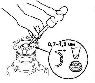
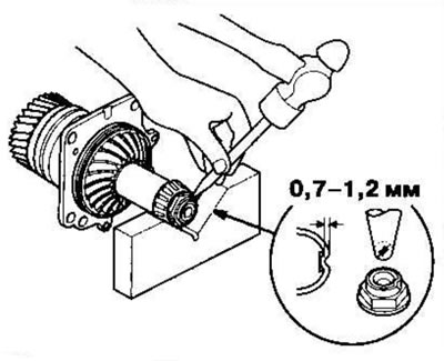
26. Use a 3.5 mm punch to counter-tap the lock nut onto the shaft of the transfer case driven gear.
27. Install the dowel pin (A) into the transfer case housing (B). Then install the transfer case holder assembly (C).
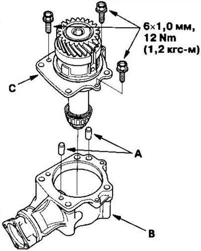
Note: Temporarily install the transfer case bracket assembly without the O-ring.
28. Clamp the transfer case housing (A) in a vice (B) with soft jaws, then rotate the coupling flange several times to seat the tapered roller bearing.
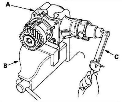
Note: To avoid damaging the transfer case housing, always secure it in a soft jawed vice or use a spacer between the vice and the transfer case.
29. Measure the total starting torque using a torque wrench (C).
Full starting torque: 1.70-2.08 Nm (17.3-21.2 kgf·cm) + the value of the starting torque of the driven gear shaft of the transfer case (recorded in p. 25).
30. Remove the transfer case holder assembly from the transfer case housing.
31. If the measurement differs from the norm, proceed to step. 32.
If the measurement is within normal limits, proceed to step. 43.
32. Secure the transfer case shaft (A) with a 14 mm wrench (B) in a vice, then loosen the lock nut.
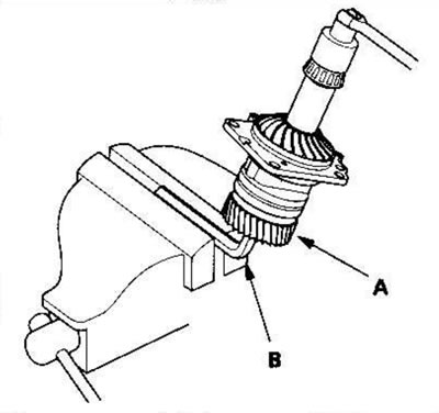
33. Loosen the lock nut (A) and remove the transfer case shaft assembly (B) from the transfer case holder (C).
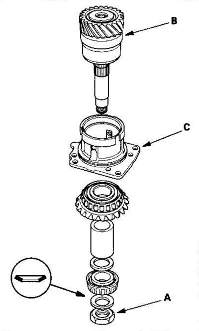
34. Press the tapered roller bearing outer race (A) and 76 mm thrust washer (B) out of the transfer case holder (C).
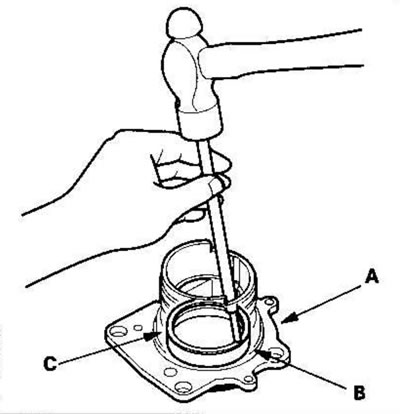
35. Measure the thickness of the removed 76 mm thrust washer and select a new 76 mm thrust washer.
Thrust washer, 76 mm
| Puck number | Catalogue number | Thickness |
| A | 41361-PPS-000 | 1.20 mm |
| IN | 41362-PPS-000 | 1.23 mm |
| WITH | 41363-PPS-000 | 1.26 mm |
| D | 41364-PPS-00O | 1.29 mm |
| E | 41365-PPS-000 | 1.32 mm |
| F | 41366-PPS-000 | 1.35 mm |
| G | 41367-PPS-000 | 1.38 mm |
| N | 41368-PPS-000 | 1.41 mm |
| J | 41369-PPS-000 | 1.44 mm |
| TO | 41370-PPS-000 | 1.47 mm |
| L | 41371-PPS-000 | 1.50 mm |
| M | 41372-PPS-000 | 1.53 mm |
| N | 41373-PPS-000 | 1.56 mm |
| R | 41374-PPS-000 | 1.59 mm |
| R | 41375-PPS-000 | 1.62 mm |
| S | 41376-PPS-000 | 1.65 mm |
| T | 41377-PPS-000 | 1.68 mm |
| U | 41378-PPS-000 | 1.71 mm |
| W | 41379-PPS-000 | 1.74 mm |
| X | 41380-PPS-000 | 1.77 mm |
| Y | 41381-PPS-000 | 1.80 mm |
| Z | 41382-PPS-000 | 1,83 MM |
| AA | 41383-PPS-000 | 1.86 mm |
| AB | 41384-PPS-000 | 1.89 mm |
| AC | 41385-PPS-000 | 1.92 mm |
| AD | 41386-PPS-000 | 1.95 mm |
| AE | 41387-PPS-000 | 1.98 mm |
| AF | 41388-PPS-000 | 2.01 mm |
| AG | 41389-PPS-000 | 2.04 mm |
| AN | 41390-PPS-000 | 2.07 mm |
| AJ | 41391-PPS-000 | 2.10 mm |
| AK | 41392-PPS-000 | 2.13 mm |
| AL | 41393-PPS-000 | 2.16 mm |
| AM | 41394-PPS-000 | 2.19mm |
| AN | 41395-PPS-000 | 2.22 mm |
| AR | 41396-PPS-000 | 2.25 mm |
| AR | 41397-PPS-000 | 2.28 mm |
| AS | 41398-PPS-000 | 2.31 mm |
| AT | 41399-PPS-000 | 2.34 mm |
| AU | 41400-PPS-000 | 2.37 mm |
| AW | 41401-PPS-000 | 2.40 mm |
| OH | 414O2-PPS-0O0 | 2.43 mm |
| AY | 41403-PPS-000 | 2.46 mm |
| AZ | 41404-PPS-000 | 2.49 mm |
| VA | 41405-PPS-000 | 2.52 mm |
| BB | 41406-PPS-000 | 2.55 mm |
| VS | 414O7-PPS-O00 | 2.58 mm |
| BD | 41408-PPS-000 | 2.61 mm |
| BE | 41409-PPS-000 | 2.64 mm |
| BF | 41410-PPS-000 | 2.67 mm |
36. Press the 76 mm thrust washer (A) into the transfer case holder (B).
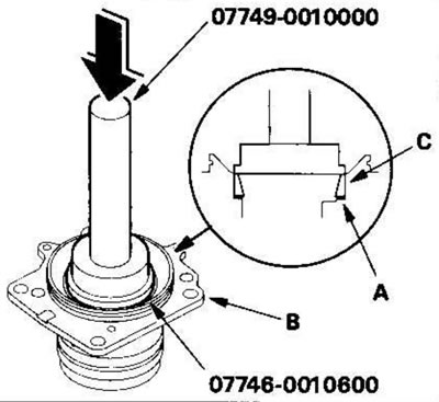
37. Press in the tapered roller bearing outer ring (C) using a special tool and a press.
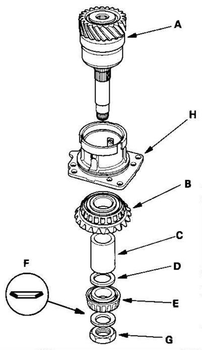
38. Install the transfer case shaft assembly (A), transfer case pinion gear (B), transfer case shaft spacer sleeve (C), 25 mm thrust washer (O), tapered roller bearing (E), tapered spring washer (F) and locknut (G) into the transfer case holder (H).
39. Secure the transfer case shaft (A) with a 14 mm wrench (B) in a vice, then tighten the lock nut.
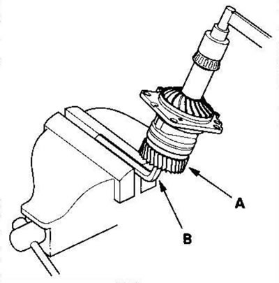
Note: Do not taper the locknut at this stage.
Tightening torque: 118 Nm (12.0 kgf·m)
40. Install the dowel pin (A) into the transfer case housing (B). Then install the transfer case holder assembly (C).
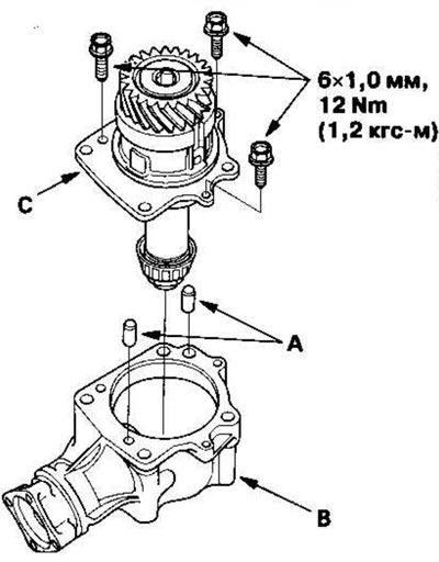
41. Recheck and ensure that the full starting torque is within the normal range.
42. Remove the transfer case holder assembly from the transfer case housing.
43. Use a 3.5mm punch to countersink the lock nut onto the transfer case shaft.
44. Apply transmission fluid to the O-ring (A), install it into the transfer case holder, then install the dowel pin (B) and transfer case holder assembly (C) into the transfer case housing (D).