
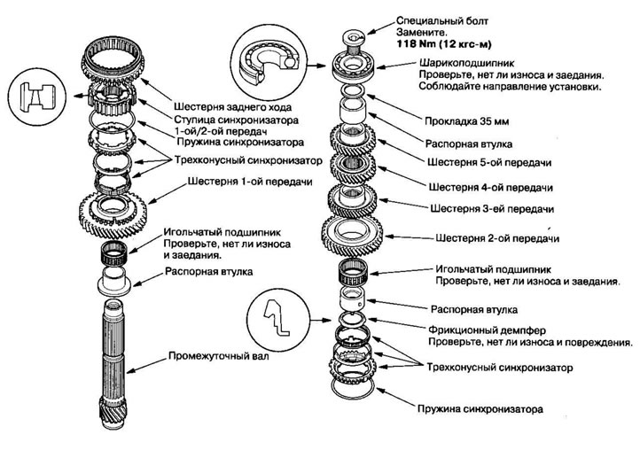
Note: When assembling, please refer to the exploded view image.
1. Before assembly, clean all parts in solvent, dry them and apply lubricant to the contact areas.
2. Install the spacer sleeve and needle bearing onto the intermediate shaft.
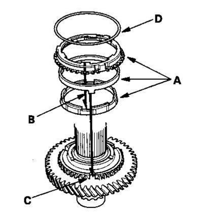
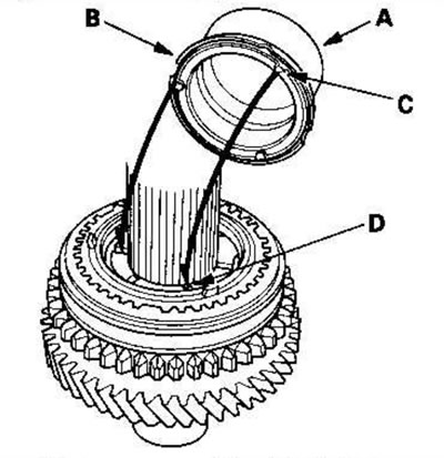
3. Install the three-cone synchronizer assembly (A) by aligning the synchronizer cone pins (B) with the slots in the 1st gear (C), then install the synchronizer spring (D).
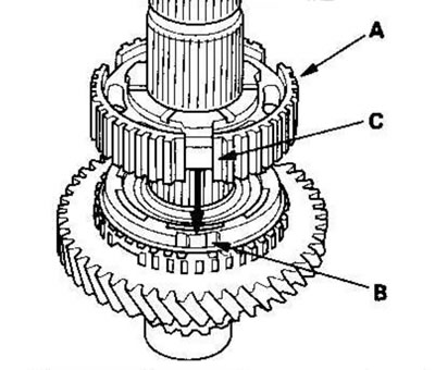
4. Install the 1st/2nd synchronizer hub (A) by aligning the synchronizer cone pins (B) with the slots in the 1st/2nd synchronizer hub (C).
5. Install the reverse gear.
6. Install the synchronizer spring (A)
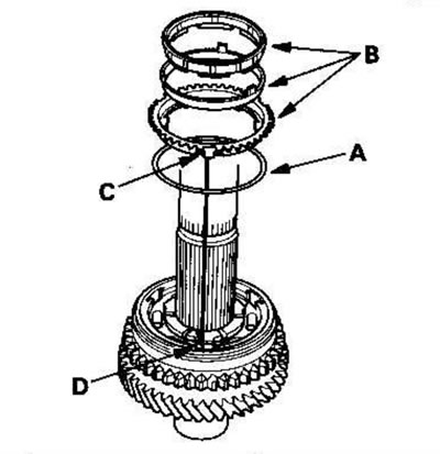
7. Install the three-cone synchronizer assembly (B) by aligning the synchronizer cone pins (C) with the slots in the 1st/2nd gear synchronizer hub (D).
8. Install the spacer sleeve (A) and friction damper (B), aligning the fingers of the friction damper (C) with the grooves in the 1st/2nd gear synchronizer hub (D).
9. Install the needle bearing.
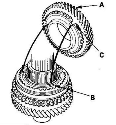
10. Install the 2nd gear pinion (A) by aligning the synchronizer cone pins (B) with the slots in the 2nd gear pinion (C).
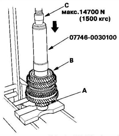
11. Mount the intermediate shaft (A) on steel blocks and press in the 3rd gear pinion (B) using the special tool and press (C). Do not exceed the maximum seating force.
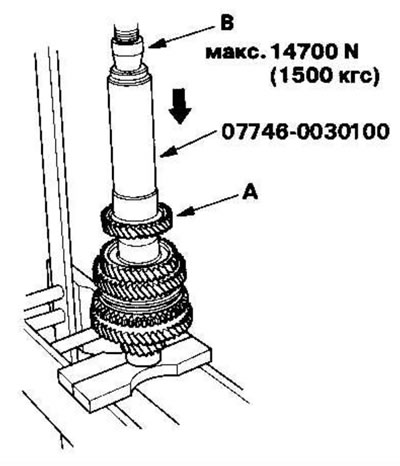
12. Press in the 4th gear (A) using the special tool and press (B). Do not exceed the maximum seating force.
13. Press in the 5th gear pinion (A) using the special tool and press (B). Do not exceed the maximum seating force.
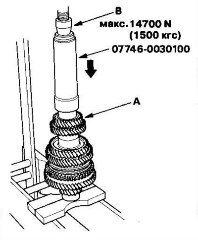
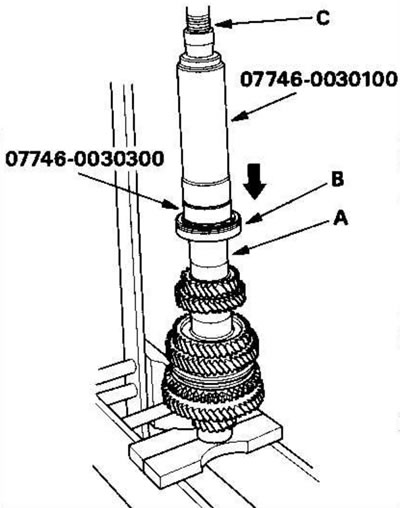
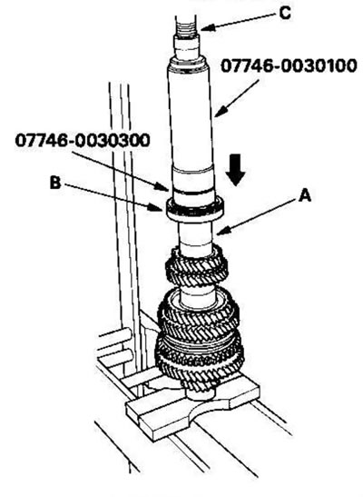
14. Press in the spacer sleeve (A), 35 mm adjusting washer and old ball bearing (B) using the special tool and press (C).
15. Measure the clearance between the old bearing (A) and the 35 mm adjusting washer (B) using a feeler gauge (C).
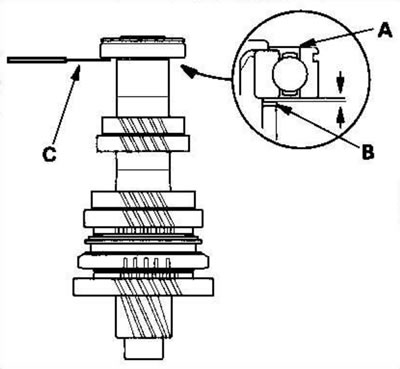
Standard: 0.04-0.10mm
16. If the clearance exceeds the specified norm, select a new adjusting washer from the following table. If the gap measured in p. 15, within normal limits, install a new ball bearing.
Adjusting washer 35 mm
| Catalogue number | Thickness | |
| A | 23981-RRR-000 | 0.87 mm |
| IN | 23981-RRR-900 | 0.91 mm |
| WITH | 23982-RRR-000 | 0.95 mm |
| D | 23982-RRR-900 | 0.99 mm |
| E | 23983-RRR-000 | 1.03 mm |
| F | 23983-RRR-900 | 1.07 mm |
| G | 23984-RRR-000 | 1.11 mm |
| N | 23984-RRR-900 | 1.15 mm |
| J | 23985-RRR-000 | 1.19 mm |
| TO | 23985-RRR-900 | 1.23 mm |
| L | 23986-RRR-000 | 1.27 mm |
| M | 23986-RRR-900 | 1.31 mm |
| N | 23987-RRR-000 | 1.35 mm |
| R | 23987-RRR-900 | 1.39 mm |
| Q | 23988-RRR-000 | 1.43 mm |
| R | 23988-RRR-900 | 1.47 mm |
| S | 23989-RRR-000 | 1.51 mm |
| T | 23989-RRR-900 | 1.55 mm |
| U | 23990-RRR-000 | 1.59 mm |
| W | 23990-RRR-900 | 1.63 mm |
| X | 23991-RRR-000 | 1.67 mm |
| Y | 23991-RRR-900 | 1.71 mm |
| Z | 23992-RRR-000 | 1.75 mm |
| AA | 23992-RRR-900 | 1.79 mm |
| AB | 23993-RRR-000 | 1.83 mm |
| AC | 23993-RRR-900 | 1.87 mm |
| AD | 23994-RRR-000 | 1.91 mm |
| AE | 23994-RRR-900 | 1.95 mm |
| AF | 23995-RRR-000 | 1.99 mm |
17. Install the ball bearing (A) on steel blocks (B) and press the intermediate shaft (E) out of the ball bearing using a press (C) and a special tool (D).
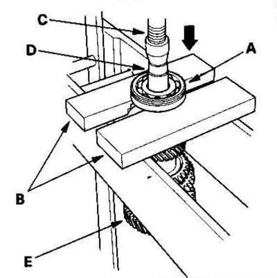
18. Replace the 35 mm adjusting washer selected in step. 16, then recheck the gap.
19. Press in the spacer sleeve (A), 35 mm adjusting washer and new ball bearing (B) using the special tool and press (C).
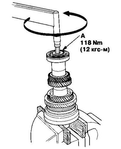
20. Tighten the new special bolt (A) (left hand thread).
Based on materials from the website www.HondaBook.ru