
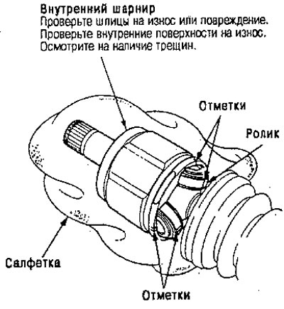
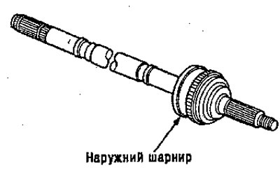
Inspection
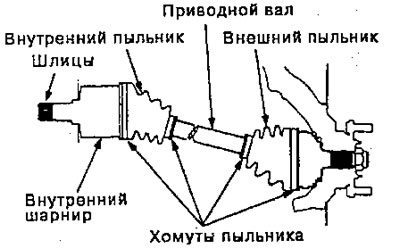
Drive shaft boot
Check the boots on the drive shaft for cracks, damage, grease leaks, or loose boot clamps.
If any damage is found, replace the boot and boot clamps.
Loosening spline joints
Rotate the drive shaft by hand and make sure that the splines and joints are not loosened excessively (do not have excessive play).
If damage is found, replace the inner joint.
Curling and cracking
Make sure the drive shaft is not twisted or cracked. Replace if necessary.
Removal
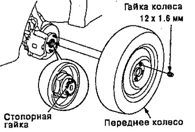
1. Slightly loosen the wheel nuts.
2. Raise the front of the machine and secure it with safety stands in appropriate locations.
3. Remove the wheel nuts and front wheels.
4. Drain the transmission fluid or oil.
Note: It is not necessary to drain the transmission oil when removing the drive shaft from the countershaft side (for machines with intermediate shaft).
5. Rivet the locking tab onto the lock nut, then remove the nut.
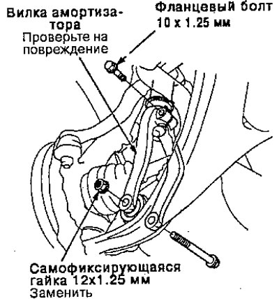
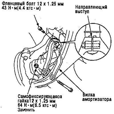
6. Remove the self-locking nut and flange bolts.
7. Remove the shock absorber fork.
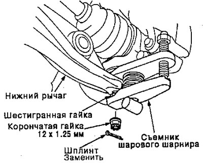
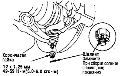
8. Remove the cotter pin from the lower control arm ball joint castle nut and remove the nut.
9. Install the M12 hex nut on the ball joint. Make sure the hex nut is in contact with the ball joint threads, otherwise the threaded part of the ball joint pin may be damaged by the ball joint puller.
10. To separate the ball joint and lower control arm, use a ball joint puller as indicated in section 18.
Attention. Be careful not to damage the ball joint boot.
Note: If necessary, apply a penetrating lubricant to loosen the contact.
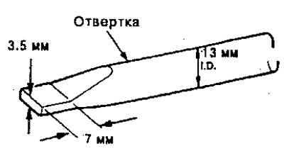
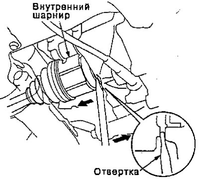
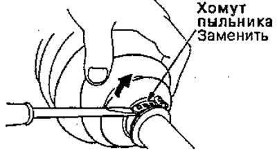
11. Push the drive shaft joint out with a screwdriver as shown to force the snap ring on the end of the drive shaft to pop out of the groove.
12. Pull the driveshaft inner joint out of the differential housing as an assembly.
Attention.
- Do not pull on the drive shaft itself, as the inner joint may separate.
- Be careful when removing the assembly and pulling it straight out to avoid damaging the differential seal or countershaft outer seal.
- With intermediate shaft:
Remove the left drive shaft from the bearing housing by tapping the drive shaft inner joint with a plastic hammer

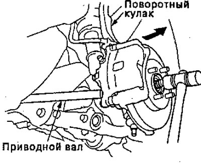
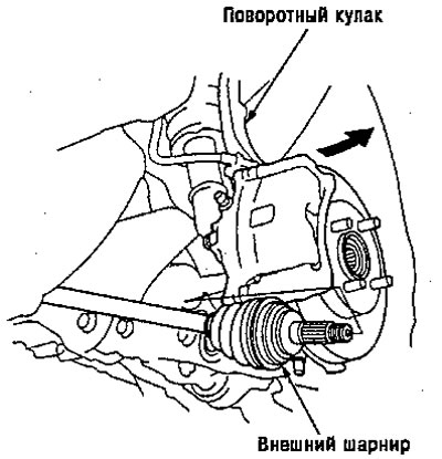
13. Pull the steering knuckle towards you and remove the drive shaft outer joint from the front wheel hub using a plastic hammer.
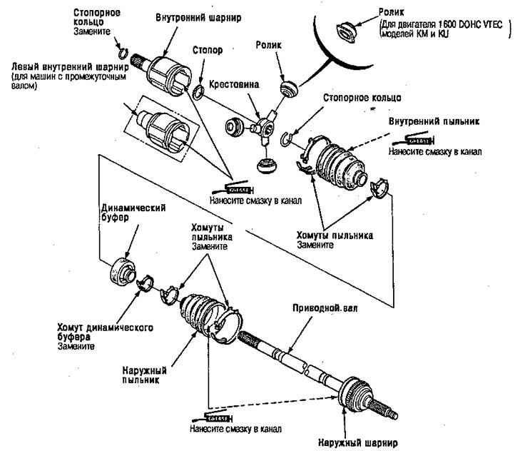
Disassembly
1. Remove the retaining ring from the inner joint groove.
2. To remove the boot clamp, lift the locking tabs up with a screwdriver and lift the end of the clamp.
Note: Carefully secure the drive shaft in a vice with soft jaws.
- If the boot clamp is a welded type, cut it as shown.
- If the boot clamp is a snap type, lift the end of the boot up with a screwdriver.
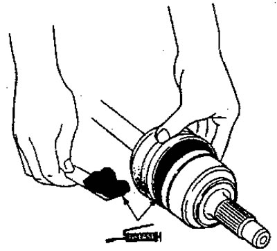
3. Mark each roller and groove on the inner joint to identify the location of the rollers and grooves on the inner joint. Then remove the inner hinge using a napkin.
Note: Be careful not to drop the rollers when removing them from the inner joint.
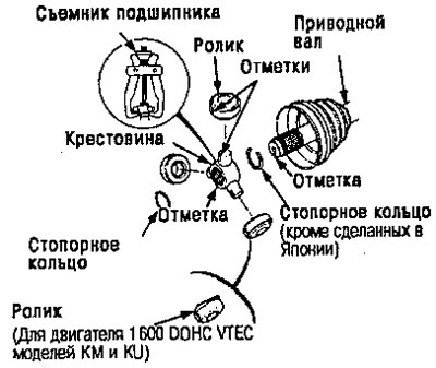
4. Mark the rollers to determine their location, then remove the rollers.
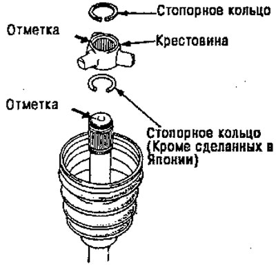
5. Remove the retaining ring.
6. Mark the spider and drive shaft to determine their relative positions.
7. Remove the spider using a commercially available bearing puller.
8. Remove the retaining ring (except for cars made in Japan).
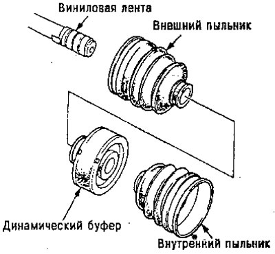
9. Wrap the splines on the drive shaft with vinyl tape to prevent damage to the boots and dynamic buffer.
10. Remove the boot clamp and the inner boot.
Attention. Be careful not to damage the boot.
11. Remove the dynamic buffer clamp, if equipped.
Attention. Be careful not to damage the dynamic buffer.
12. Remove the boot clamps and outer boot, then remove the vinyl tape.
Attention. Be careful not to damage the boot.
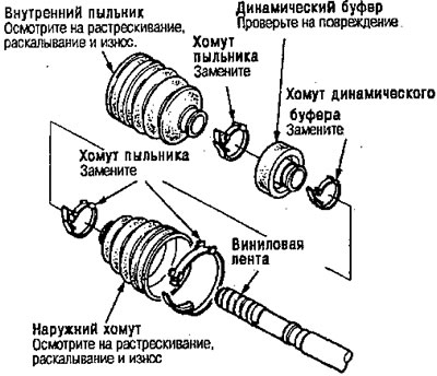
13. Inspect the outer joint for abnormal movement and wear.* If there is uneven movement and excessive play, replace the outer joint.
Assembly
Note:
- Clean the disassembled parts with solvent and dry thoroughly with compressed air. Do not wash rubber parts with solvent.
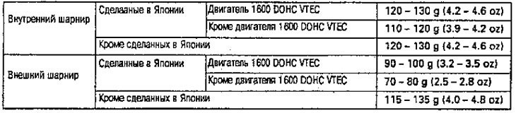
- Thoroughly coat the inner joint and both joint boots with the joint grease included with the new drive shaft.
Lubricant quantity:
1. Wrap splines with vinyl tape to prevent damage to boots and dynamic buffer.
2. Install the outer boot, dynamic buffer and inner boot onto the drive shaft, then remove the vinyl tape.
Attention. Be careful not to damage the boots and dynamic buffer.
3. Install the retaining ring into the groove of the drive shaft (except for cars made in Japan).
Note: Always rotate the retaining ring in its groove to ensure it is fully seated.
4. Install the crosspiece onto the drive shaft, aligning the marks on it and the end of the drive shaft.
5. Install the retaining ring into the groove of the drive shaft.
Note: Always rotate the retaining ring in its pocket to ensure it is fully seated.
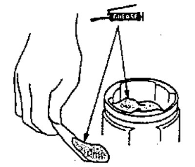
6. Apply the joint grease supplied with the new drive shaft kit to the outer joint.
Lubricant quantity:
- Made in Japan
- Engine 1600 DOHC VTEC 90-100 g.
- Except for the 1600 DOHC UTES engine: 70-80 g.
- Except for those made in Japan 115-135.
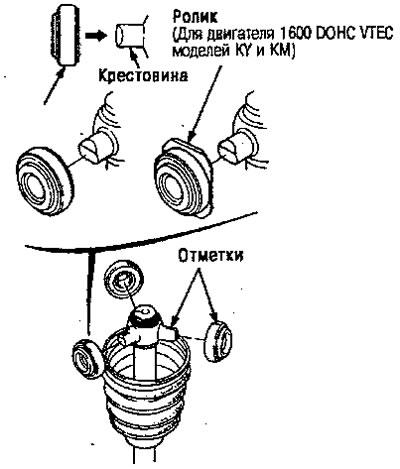
7. Place the rollers on the crosspiece so that their protrusions point outward.
Note:
- Place the rollers in their original position on the crosspiece, aligning the marks.
- Keep the drive shaft vertical to prevent the rollers from falling.
8. Apply the joint grease supplied with the new driveshaft kit to the inner joint.
Lubricant quantity:
- Made in Japan
- Engine 1600 DOHC VTEC 120-130 g.
- Except for the 1600 DOHC VTEC 110-120 engine.
- Except for those made in Japan 120-130 g.
9. Insert the inner joint into the drive shaft.
Note:
- Install the inner joint to the drive shaft, aligning the marks on the inner joint and the rollers.
- Keep the drive shaft vertical» so that the rollers do not fall.
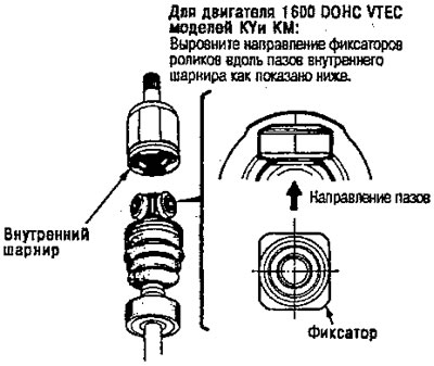
For the 1600 DOHC VTEC engine of the KUi KM models:
Align the direction of the roller locks along the grooves of the inner joint as shown below
10. Adjust the length of the drive shafts as indicated below, then adjust the boots halfway between full compression and full tension.
Note: the ends of the anthers fit into the holes of the drive shaft and hinge.
Drive lengths are for models from 1996 onwards
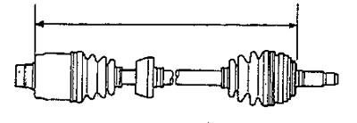
LHD 1600 DOHC VTEC Engine: 475-480mm.
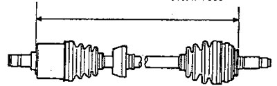
- Right-hand drive 1800 DOHC VTEC engine: 475-480 mm.
- Left-hand drive except 1600 DOHC VTEC engine: 774-779 mm.
- Right-hand drive except 1600 DOHC UTES engine: 501-506 mm.
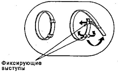
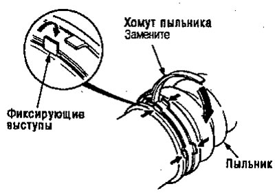
11. Install new boot clamps and bend both fixing tabs.
12. Tap the tabs lightly to reduce their protrusion.
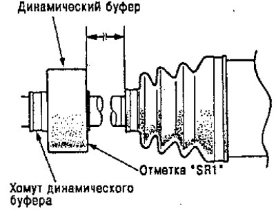
13. Place a dynamic buffer as shown below.
- Install a new dynamic buffer clamp and bend the locking tabs down.
- Tap lightly to reduce protrusion.
For models from 1996 release
Left:
- Engine 1600 DOHC UTES 26±2 mm.
- Except 1600 DOHCVTEC 94±2mm engine.
- With mark "SR1": 75±2 mm.
Right:
- Engine 1600 DOHC UTES 26±2 mm.
- Except 1600 DOHC VTEC 55±2mm engine.
Installation
1. Install the outer joint into the steering knuckle.
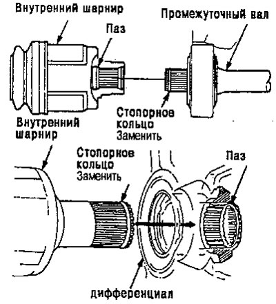
2. Apply 0.5 - 1.0 g of the specified lubricant to the entire spline surface of the intermediate shaft,
Note: After applying the grease, remove the grease from the spline grooves at 2-3 spline intervals and from the snap ring groove to allow air to escape from the inner joint.
3. Install a new snap ring into the drive shaft or countershaft groove.
Caution: Whenever you install the drive shaft, always use a new snap ring.
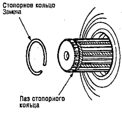
4. Insert the inner end of the drive shaft into the differential or intermediate shaft until the snap ring locks into the hole.
Note: Thoroughly clean the area where the transmission {differential) contacts the drive shaft, solvent or carburetor cleaner and dry with compressed air.
5. Install the steering knuckle onto the lower control arm, then tighten the castle nut and install a new cotter pin.
Note: Remove any grease before tightening the ball joint nut.
Attention:
- Be careful not to damage the ball joint boot.
- Tighten the nut to the lower rated torque, then until the slot is aligned with the hole for the cotter pin.
6. Install the shock absorber fork through the drive shaft onto the lower arm. Install the shock absorber into the shock absorber fork so that the guide lug aligns with the slot in the shock absorber fork.
7. Install the flange bolt and new self-locking nut without tightening.
Note: The bolt and nut must be tightened when the weight of the vehicle is pressing on the shock absorber strut.
8. Install the new lock nut, then tighten it.
9. Install the front wheel and wheel nut
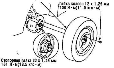
Note: After tightening, use a punch to secure the lock nut to the drive shaft shank.
10. Tighten the flange bolts and new self-locking nut with the vehicle's weight on the shock absorber.
11. Fill the transmission with the recommended oil or fluid.
12. Check the front wheel alignment and adjust if necessary.