
Examination
Label all wires on the module before removing.
Models CR-V
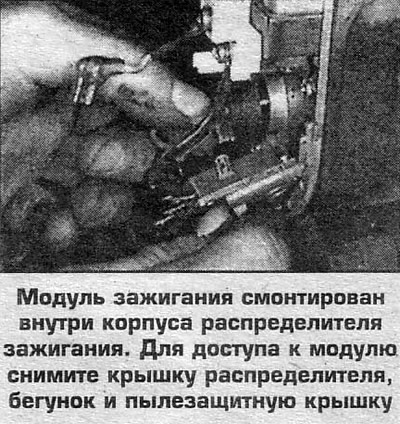
1. Remove the distributor cap and slider, label and disconnect the wires from the module.
2. Turn on the ignition and check for battery voltage between ground and the black/yellow wire. If there is no voltage, then check the circuit between the ignition switch and the black / yellow wire of the module.
3. With the ignition on and check for battery voltage between ground and the white/blue wire. If there is no voltage, then check the ignition coil and the presence of a break in this wire.
4. Disconnect the connector on the motor processor unit and check the continuity between the yellow/green wire leads on the processor unit and on the module. If there is no circuit, check for an open in this wire, check the continuity between the yellow/green wire and ground (there shouldn't be a chain).
5. On 1997-98 models. check for a continuity between the blue wire of the ignition module and the tachometer connector (mounted on the wall of the engine compartment). Make sure there is no short to ground on this wire.
6. The module is considered faulty if, after troubleshooting the wires (breaks or short circuits) all test results are negative.
4-cylinder Odyssey
On 1995 models, disconnect the black/yellow (1) and blue (2) wires.
On models 1996-97. disconnect the yellow/green, black/yellow and blue wires from the module.
On 1998 models disconnect the yellow/green and black/white wires from the module.
1. With the ignition on, check for battery voltage between the black/yellow wire and ground. If there is no voltage, then check the circuit between the ignition switch and the black/yellow wire terminal.
2. With the ignition on, check for battery voltage between the white/black wire (1996-97), or blue wire (2) by wire (1995), and mass. If there is no voltage, then check the ignition coil and the presence of an open in these wires between the coil and the module.
3. Disconnect the connector on the motor processor unit and check the continuity between the yellow/green wire terminals on the processor unit and on the module. If there is no circuit, check for an open in this wire, check the continuity between the yellow/green wire and ground (there shouldn't be a chain).
5. On 1995 models, check for continuity between the blue wire (1) ignition module and the corresponding terminal of the transmission control unit connector (TCM - module). Make sure there is no short to ground on this wire.
6. On 1996-97 models. check the circuit between the blue wire output and the tachometer connector (mounted on the wall of the engine compartment on the right side). Make sure there is no short to ground on this wire.
7. The module is considered faulty if, after troubleshooting the wires (breaks or short circuits) all test results are negative.
Removal and installation
1. Remove the distributor cap and slider, label and disconnect the wires from the module.
2. Disconnect the wires from the module.
On CR-V models, disconnect the yellow/green, black/yellow, and white/blue wires from the module.
On 4-cylinder Odysseys:
- on the 3-pin connector, disconnect the yellow/green, black/yellow and white/black wires from the module.
- on the 4-pin connector, disconnect the harness with black / yellow, blue and yellow / green wires, disconnect black / white or blue from the module (1) wire and separate blue (2) the wire.
3. Turn away screws of fastening and remove the module.
4. Assembly is carried out in the reverse order.