
Examination
1. Remove the ignition coil cover.
2. Label and disconnect connectors from all 6 coils.
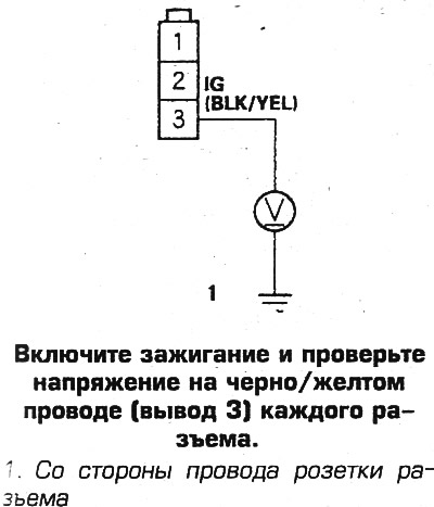
3. Turn on the ignition and check the voltage on the black/yellow wire of each connector. If there is no voltage, then check and repair the circuit between the coil and fuse N11, which is located on the left side of the mounting block under the instrument panel.
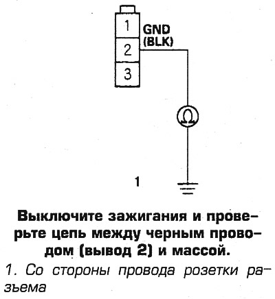
4. Switch off ignitions and check up a chain between a black wire and weight. If there is no chain, then repair the chain between the coil and ground.
5. If there is a ground circuit, then disconnect the 31-pin connector from the processor unit and check the ground circuit at the following connector pins:
- pin 3, blue wire
- pin 4 yellow/green wire
- pin 12 red/black wire
- pin 13 yellow wire
- pin 4 red wire
- pin 23 white/blue wire
In this case, it should be taken into account that the terminals 1-11 of the connector are located in the upper row of the connector (when viewed from the side to be connected, the connector key must be facing up, counting from right to left), pins 12-22 - in the second row, pins 23-31 - in the third row, connector sockets for pins 11 and 24 are empty.
If there is a ground circuit, repair the short to ground in the corresponding wire.
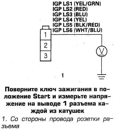
6. If there is no ground circuit, then connect the connector, turn the ignition key to the Start position and measure the voltage at the following terminals of the connectors of each of the coils: blue, yellow / green, black / red, yellow, red and white / blue.
If the voltage is 0.5 V, then replace the coil. If there is no voltage, then repair the circuit between the processor unit and the coil.
Removal and installation
1. Remove the clamping coil cover.
2. Label and disconnect connectors from all 6 coils.
3. Turn away bolts and remove the coil.
4. Installation is carried out in the reverse order.
Electronic ignition module
The ignition module is built into the coil and changes with the coil.