
Warning! The car models covered in this manual are equipped with an additional security system (SRS). Before doing any work near the airbag unit, steering column or instrument panel, turn off the SRS to avoid injury if it is accidentally deployed (see chapter Onboard electrical equipment). SRS circuit wiring is easily identified by the yellow color of the insulation.
General information
All AT-equipped models have a locking system to prevent unintentional gear changes. The locking system consists of two subsystems: the shift lock system and the key lock system.
Key lock system
The system prevents the key from being removed from the ignition switch until the selector lever is moved to the "R". When a key is entered into a lock in any other "R" position of the lever, the electromagnetic actuator is activated, making it impossible to remove the key. To remove the key, move the lever to the desired ("R") position.
Shift lock system
The system prevents the selector lever from being moved out of position "R" into the provisions "R" or "D" without depressing the foot brake pedal. The lock is also activated when the brake and accelerator pedals are depressed at the same time. In the event of a system failure, the lever can be unlocked by inserting a key into a special slot near the lever assembly.
Examination
1. The following checks of the electromagnetic actuators of both interlocks can be done on their own by an amateur mechanic at home. A more detailed diagnosis of the system should be performed in a car service workshop.
Note. Electromagnetic ignition key lock actuator
2. Remove the lower trim section of the instrument panel and knee brace (see chapter Body).
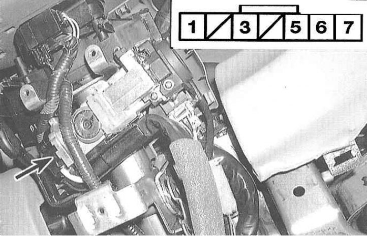
3. Disconnect the 7-track connector of the main wiring harness.
4. Check up a socket on existence of conductivity between plugs in various provisions of the switch of ignition. When the key is sunk into the lock between terminals 5 and 7 of the connector, conduction should take place, when the key is released, no.
5. Make sure that key removal is not possible when battery voltage is applied to terminals 7 (+) and 3 (-).
6. If the key cannot be removed, then the locking system is functioning properly, otherwise it is necessary to replace the ignition switch assembly (see chapter Onboard electrical equipment). Blockers are not issued individually.
Note. Solenoid shift lock actuator
7. Remove the console (see chapter Body).
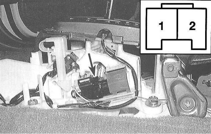
8. Disconnect the shift lock solenoid 2-track connector.
9. Using the two jumper wires, momentarily connect the battery to the connector terminals (positive pole - to terminal 1, negative - to terminal 2), - when power is applied, the possibility of switching the lever must be absent, otherwise the device must be replaced.
Attention! Reversing the polarity of the battery connection is fraught with failure of the diode inside the electromagnetic assembly.
10. Remove the jumper wires and move the selector lever back to the position "R".
11. Make sure the lever lock disengages when pushed in and re-engages when released.
Note. Gear Selector Lever Position Sensor
12. Remove the center console (see chapter Onboard electrical equipment).
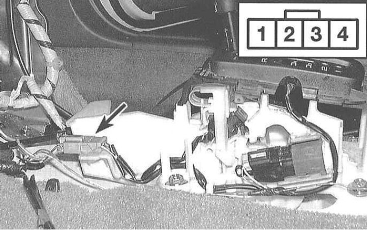
13. Disconnect the 4-pin connector of the sensor-switch of the position of the selector lever in the area of the center console.
14. Move the lever to position "R" and check for continuity between terminals 3 and 4 of the connector.
15. Now move the lever to the position "N", - continuity between terminals 3 and 4 should disappear.
16. At negative results of the check described above replace the gauge switch.
Replacement and adjustment of the electromagnetic actuator
Note. The procedure below applies to the shift lock only. Information on replacing the ignition key lock solenoid actuator is given in the Section on replacing the ignition lock cylinder (see chapter Onboard electrical equipment).
1. Remove the center console (see chapter Body).
2. Disconnect the 2-pin connector of the electrical wiring of the electromagnetic actuator.
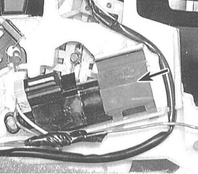
3. Prying off, remove the actuator retainer.
4. Remove the actuator assembly with plunger and plunger spring.
5. Installation is carried out in the reverse order.