Removal and installation
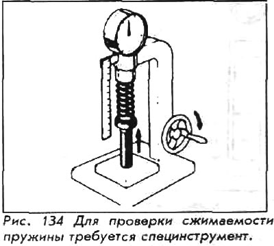
A special puller is required to remove the valves and springs. A small magnet can be very useful for extracting cotters and spring washers.
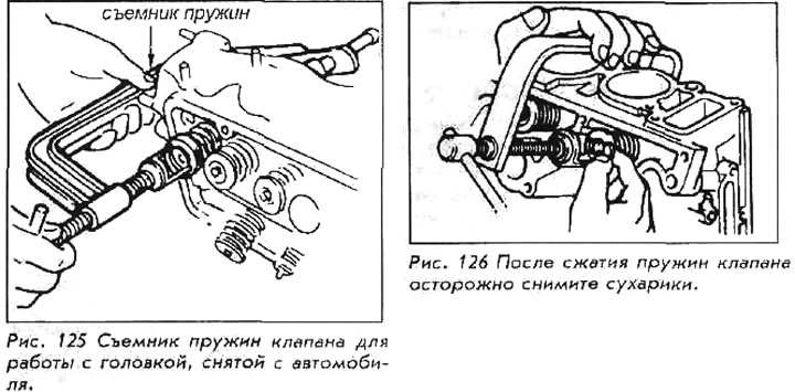
Place the cylinder head on its side on a stand. Install the spring extractor so that the thrust side of the tool is flat against the valve head in the combustion chamber and the screw side is against the spring cup. Slowly turn the screw towards the plate, compressing the spring. After the spring is compressed, crackers will appear; collect them with a magnet, as they easily slip out of your hands and get lost. When the crackers are removed, return the puller screw and remove the plates and springs. Remove the puller and remove the valves from the other side of the head. Remove the valve stem seals by hand and remove the valve spring retainers with a magnet.
Since it is very important that each valve (its spring, plate and spring washer and crackers) reassembled from the same kit, you must keep these parts from mixing. The best way to do this is to make a holder - cut holes in a piece of hard cardboard. Label each port with the cylinder number and valve name Vp. or Issue., corresponding to the position of each cylinder and valve in the head. As you remove each valve, insert it into the holder and assemble the washers, springs, cotters and poppets on the valve stem on the marked side of the holder. In this way, each valve and its parts are kept together and can be put back into the head in the correct position.
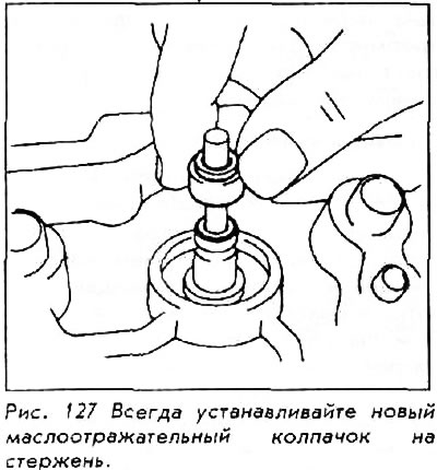
After lapping each valve in its seat (see Valve Lapping) the valve stem is lubricated and each valve is installed in the head in the reverse order of removal, so that all parts, except crackers, are assembled on the stem. Always use new valve stem seals.
Install the spring extractor, compress the poppet and spring until the keyway on the valve stem is fully open. Fill the groove with grease and install both nuts with the wide end up. Slowly return the screw of the puller until the spring plate covers the crackers. Remove the tool. Lightly tap the end of the stem of each valve with a rubber mallet to ensure that the poppets and biscuits are properly seated.
Inspection
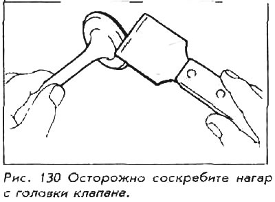
Before the valves are inspected, the stem, its lower end and the entire surface of the valve and head must be cleaned. Old valves are good for scraping carbon off the valve head, and a wire brush or scraper can be used to clean the end of the valve and the area between the end and bottom of the stem. Do not scratch the valve face when cleaning. Clean the entire rod with a rag soaked in carbon thinner.
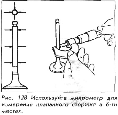
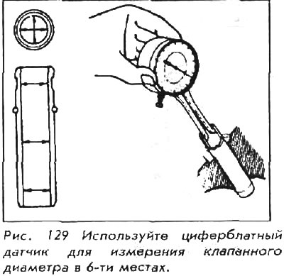
A complete inspection of the valves requires the use of a micrometer and a dial gauge to measure the inside diameter of the valve guides. If these tools are not available to you, the valves and head can be taken to the workshop. Refer to the table VALVE SPECIFICATION for checking valve stems and guides. If the above tools are at your disposal, measure the diameter of each valve stem at the top, middle and bottom. Measure in two directions (when viewed from above the rod). That's six measurements per valve; record these measurements from top to bottom in order for each valve.
Using a dial gauge, measure the inside diameter of the valve guides at their base, top, and midpoint, again in two directions. Six measurements for each guide; also record these measurements.
Subtract the measured valve stem size from the measured guide inner diameter; if clearances are greater than specification for stem-to-guide clearance, replace valve (s). The rod-guide gap can also be checked in a machine shop that has a dial gauge.
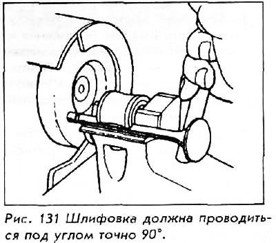
Check the top of each valve stem for pitting, bending, and abnormal wear due to incorrect rocker arm adjustment. Due to wear, the tip of the rod may be flattened. If more than a little sanding is required to make the tip flat and smooth, the valve must be replaced. When grinding, make sure you lock the valve securely in a jig designed for this purpose so that the tip comes into contact with the grinding wheel perpendicularly at an angle of exactly 90°. Most mechanical workshops that are designed to work on cars are equipped for this job.
Regrinding
Valve regrinding should only be done by a reputable mechanic shop, as the experience and equipment required for this job is not available to the average auto mechanic owner. In the process of working on valves, regrinding is necessary when simple lapping of the valves into their seats does not correct the wear of the seats and ends. Valve seats can also be cut, but this requires special equipment and experience.
Valve lapping
Valves must be lapped into their seats after regrinding to ensure a good seal. Even if the valves have not been reground, they must be lapped into the head before reassembly. Lapping is nothing more than very fine polishing of a metal to obtain a precise fit between two contact surfaces.
Place the cylinder head on a work stand, combustion chamber side up. Mount the head on wooden blocks at each end, so that there is 5-8 cm between the tops of the valve guides and the stand.
1. Lightly lubricate the valve stem with clean machine oil. Coat the valve seat completely with valve lapping compound. Use ONLY enough compound to cover the entire surface of the saddle.
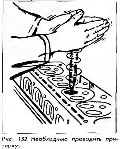
2. Set the valve to its natural position in the head. Attach the end of the valve lapping tool with the suction cap to the valve head. A small amount of saliva in the suction cap will usually help it attach to the valve.
3. Rotate the instrument between your palms, changing position frequently and lifting the instrument to prevent grooves. Lap the valve until the seat and valve face are smooth and evenly polished.
4. Remove the valve from the head. Wipe off all traces of lapping compound from the valve face and seat. Wipe the hole with a solvent-soaked rag and coat the valve guide with a piece of solvent-soaked rag to ensure there are no traces of compound particles inside the guide. This cleaning is important, if the compound is not removed, it will grind the parts inside the engine during operation.
5. Lap in the remaining valves one at a time. Make sure the valve ends, seats, cylinder bores and valve guides are clean before reassembling the valve bank.
Valve springs
Inspection
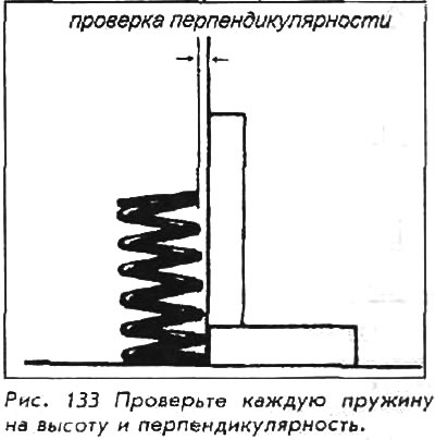
The perpendicularity, length and extension of the valve spring must be checked during disassembly of the valve bank. Place each valve spring on a flat surface next to a steel square. Measure the length of the spring, and rotate it around the edge of the square to measure the deflection. If the length of the spring is different (when comparing) more than 1.0 mm or if the curvature exceeds 1.0 mm, replace the spring.
Spring extension should be checked with a spring tester. The springs used on most Honda engines should be within ½ kg of each other when tested at specific heights.