
Removal
Engine temperature must be below 38°C. To facilitate installation, make sure piston number 1 is at Top Dead Center before removing the camshaft.
1. Remove the valve cover.
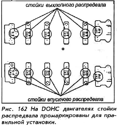
2. Remove the distributor or camshaft position sensor from the end of the camshaft.
3. Remove the camshaft pulley retaining bolt and washer and remove the camshaft pulleys together with the Woodruff keys, if equipped.
4. Before removing the rocker arm assembly, measure the camshaft end clearance as follows:
Do not rotate the camshaft during the check. Loosen the rocker arm adjusting screws before starting.
- a. Install the camshaft by moving it towards the end where the distributor is located.
- b. Install a dial indicator on the end of the camshaft. Set the zero of the dial indicator against the end of the distributor drive, then move the camshaft back and forth, determine the axial clearance; do this for both camshafts.
- c. The standard camshaft end play for a new camshaft is 0.05-0.15mm.
- d. The standard service limit for camshaft end play is 0.5mm.
5. Loosen the camshaft strut and rocker arm shaft bolts in a crosswise pattern, starting from the outer strut.
6. Remove the rocker arms, axles and struts as an assembly.
7. Remove the camshafts.
8. Wipe the camshaft clean, then inspect the cam lobe surfaces. Replace the camshaft if the cam lobe surfaces are corroded, scored, or excessively worn.
If the radial clearance of the camshaft bearings is outside the tolerance limits, and the camshaft has already been replaced, then the cylinder head must be replaced.
To install:
9. After cleaning the surfaces of the camshaft and the journals, lubricate both surfaces with aggregate grease and install the camshaft.
10. Turn the camshaft until the keyway faces upward (cylinder number 1 at Top Dead Center).
11. Install the rocker arms in their original positions. Place the rocker arms on the pivot bolts and valve stems. The valve lock nuts must be loosened and the adjusting screws turned out before installation.
12. Install the camshafts and camshaft seals with the open side (spring) facing in. When installing the camshaft struts, note that each is marked with a letter, number and arrow. The arrow faces the front of the engine and each strut MUST be installed correctly: E1 is the first on the exhaust side and l6 is the last on the intake side.
13. Apply liquid gasket to the cylinder head surface that mates with camshaft posts number 1 and number 6, then install these posts along with posts number 2, 3, 4 and 5.
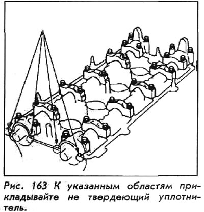
14. Make sure the rocker arms are correctly positioned on the valve stems and temporarily tighten the camshaft struts.
Use a non-hardening material to seal the cylinder head surface on each side adjacent to the camshaft(s) seals.
15. Using a seal installation tool of the correct diameter and length, install new camshaft seals.
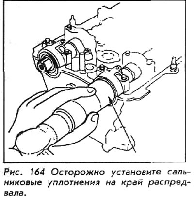
16. Tighten each rocker arm bolt in two-turn increments in the proper sequence, working from the center and spiraling outward. Take care to prevent the rocker arms from pinching the valves.
17. Install the keys into the camshaft grooves. Slide the camshaft pulleys onto the camshaft, then install a new washer with a locking bolt.
To set cylinder number 1 to top dead center, align the hole in the camshaft with the hole in the number one camshaft post and insert a 5 mm pin into the holes.
18. Install the distributor or camshaft position sensor.
19. Adjust the valves.
20. Install the valve cover.
Inspection
The camshaft must be handled with care; it will be damaged if dropped or subjected to a sharp impact.
Remove grease from the camshaft using a non-hazardous solvent. Clean all oil grooves and passages. Inspect the camshaft lobes and journals for wear. If in doubt, check all lobes and journals with a micrometer. A worn camshaft will result in short service intervals or frequent oil and filter changes.
Measure the cam lobe from nose to base and again at 90°. The lift is determined by subtracting the second measurement from the first. If all the exhaust cams and all the intake cams are different heights (compare intake cams to intake cams and exhaust cams to exhaust cams), the camshaft must be replaced. Measure the cam journals and compare to the chart in this Chapter. If the journal is worn, the camshaft must be replaced.
If the cams and journals appear undamaged, place the front and rear bearing journals of the camshaft in the V-blocks and attach a dial indicator to the center journal. Rotate the camshaft to check its straightness, if the deviation exceeds 0.025 mm, replace the camshaft.
(The text of the article is available on the website: HONDABOOK.ru)