
Withdrawal
1. Disconnect the cable from the negative battery terminal.
2. Turn the crankshaft pulley so that the piston of cylinder No. 1 is in the TDC position on the compression stroke. In this position, turning the crankshaft and camshaft is prohibited.
3. Drain the coolant from the radiator. Use a clean, dry container to drain, cap container, and thoroughly drain any spilled liquid.
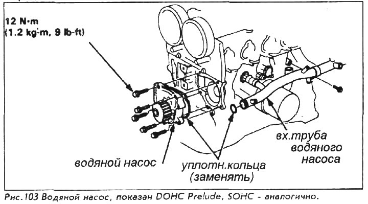
4. Remove the engine mounting bolts and nuts, then remove the side support and strut rubber. Remove the cruise control actuator, if equipped. Take it out of the work area without disconnecting or twisting the cable.
5. Remove the mudguard from below the engine.
6. Loosen the power steering pump belt adjusting nut and remove the belt. Remove the adjusting pulley and power steering pump. Slide the pump along with the hoses.
7. Disconnect the wires from the generator, remove the generator through bolt, adjusting and mounting bolts and remove the belt and generator.
8. On vehicles with air conditioning, remove the compressor mounting bolt. Remove compressor and belt. Do not disconnect the hoses from the compressor, take it out of the working area and fix it with a hard wire.
9. On vehicles with fuel injection, remove the ignition wires from the valve cover and the wire harness guard from the cylinder head.
10. Remove the valve cover.
11. Remove the crankshaft bolt and crankshaft pulley.
This bolt is one of the tightest bolts in a car's design. While loosening the bolt, the pulley is held by the old belt, but the pulley should not be supported by the belt you are about to reinstall on the vehicle. As a result, the belt stretches or breaks.
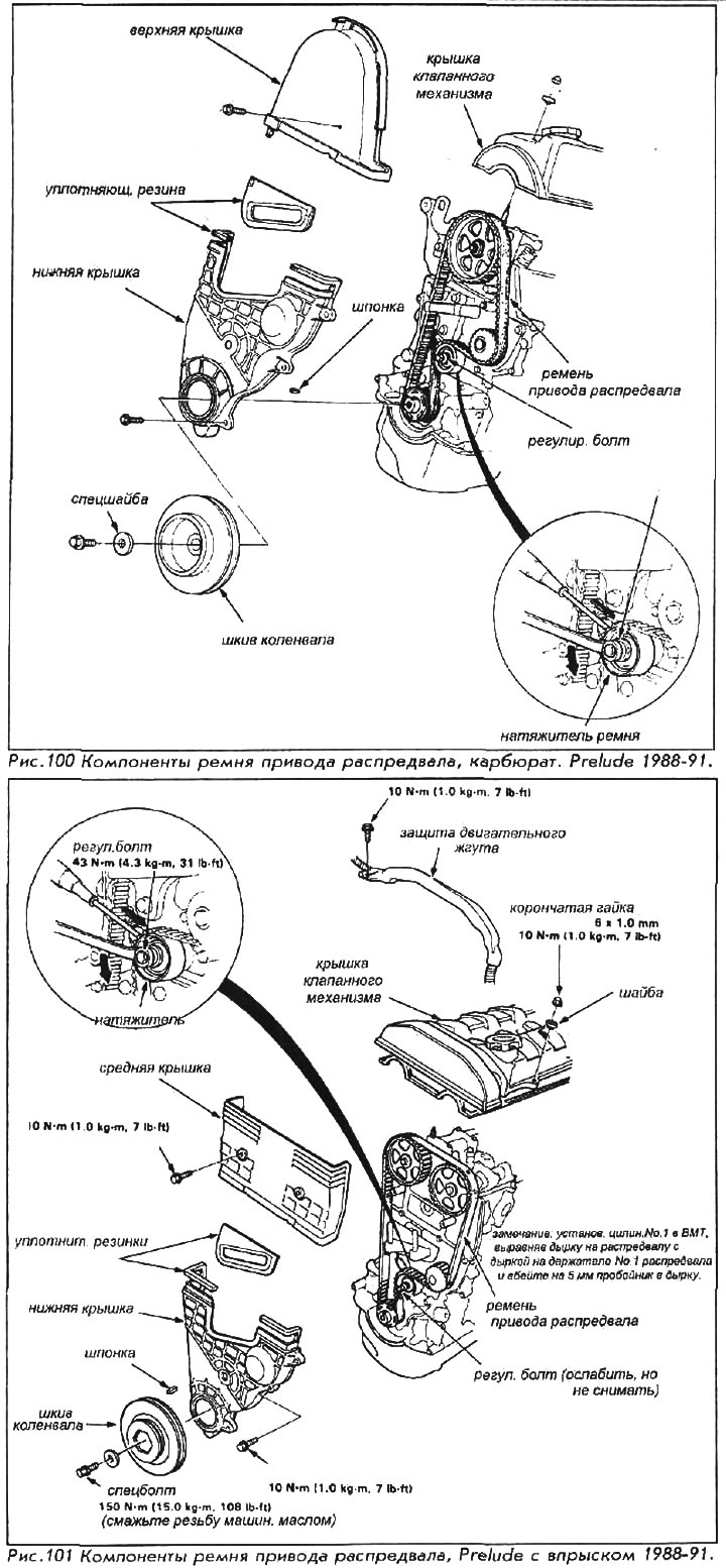
12. Remove the camshaft drive belt covers.
13. Loosen but do not remove the adjusting bolt on the camshaft belt tensioner. Slide the adjuster off the belt and tighten the bolt.
14. Using chalk or a marker, mark an arrow on the camshaft drive belt. The arrow will indicate the direction of rotation or the outer edge of the belt. The belt must be reinstalled so that it runs in the same direction. Carefully remove the belt from the pulley without twisting it and protecting it from oil and coolant.
15. Remove water pump mounting bolts, pump and o-ring.
For installation:
16. Install a new o-ring and pump. Make sure the O-ring is not deformed or misaligned. Tighten the mounting bolts to 12 Nm.
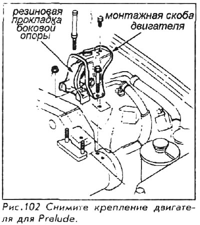
17. Double check the position of the crankshaft: the number one cylinder should be at top dead center on the compression stroke. All of the following must be observed: The pointer on the back of the cylinder block must align with the white mark on the flywheel or drive plate (for automatic transmission). Tagging "UP" on each camshaft pulley must be at the top, and the corresponding marks on all camshaft pulleys are aligned with the surface of the cylinder head.
On fuel injected engines, each camshaft can be secured in the top dead center position with a 5mm punch in the service holes immediately behind each camshaft pulley. This greatly simplifies the installation of the belt.
18. Install the camshaft drive belt so that it rotates in the same direction as before, remove the pins holding the camshafts if you installed them.
19. Loosen the adjuster and allow it to tighten the belt, then tighten the adjusting bolt.
20. Install the belt covers, except for the top cover on engines with a single camshaft.
21. Install the crankshaft pulley and key. Coat the threads of the bolt with clean oil, but do not lubricate the surface of the bolt in contact with the washer. On engines with fuel injection, tighten the bolt to 150 Nm, and on carbureted engines to 115 Nm.
This bolt is to be tightened with the wheels locked, the parking brake applied and the gear engaged for a manual transmission or for an automatic transmission, set the selector lever to position "PARK".
22. Turn the crankshaft counterclockwise until the camshaft pulley rotates 3 sectors (prong). Loosen the adjusting bolt, then tighten it to 43 Nm.
23. Install the valve cover and top belt cover on carbureted engines. On a fuel injected vehicle, install the ignition wires and harness guard.
24. Install the air conditioning compressor and belt. Tighten the mounting bolts to 25 Nm. Adjust belt tension.
25. Install alternator and belt. Tighten the through bolt to 45 Nm.
26. Install the power steering pump, tighten the bolts to 27 Nm.
27. Install the side engine support and cruise control drive, if removed. Tighten the motor mounting bolts to 40 Nm and the nuts to 65 Nm.
28. Fill the cooling system with coolant.
29. Connect the cable to the negative battery terminal.
30. Start the engine at idle. Check the work area for signs of fluid leakage and belt thumping sound or connections vibrating.
31. Turn off the engine and install the lower mudguard.