


Programmable fuel injection system PGM-FI Honda Accord 3

General description of the programmable injection system
Accord and Prelude models 1990-91 The Programmed Fuel Injection (PGM-FI) system is a fully electronic engine management system based on a microprocessor. The Electronic Control Unit (ECU) is responsible for:...
Accord and Prelude models 1990-91 The Programmed Fuel Injection (PGM-FI) system is a fully electronic engine management system based on a microprocessor. The Electronic Control Unit (ECU) is responsible for:...
Electronic Control Unit (ECU)
In order to deliver fuel to the cylinders at the right time and in the right amount, the control system must perform various functions. The ECU is the heart of the programmable fuel injection system (PGM-Fl). It uses a...
In order to deliver fuel to the cylinders at the right time and in the right amount, the control system must perform various functions. The ECU is the heart of the programmable fuel injection system (PGM-Fl). It uses a...
Sensors and inputs
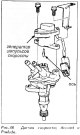
Crankshaft, TDC and CYL sensors The Crankshaft Angle Sensor (CRANK) signal is used to determine the injection timing and ignition timing, and to determine the engine speed. The TDC sensor signal is used to determine the...
Crankshaft, TDC and CYL sensors The Crankshaft Angle Sensor (CRANK) signal is used to determine the injection timing and ignition timing, and to determine the engine speed. The TDC sensor signal is used to determine the...

ECU controlled output signals
The main purpose of the ECU is to maintain a good level of performance in all situations. The ECU interprets and compares various input signals from sensors and uses the resulting calculations to control the level of...
The main purpose of the ECU is to maintain a good level of performance in all situations. The ECU interprets and compares various input signals from sensors and uses the resulting calculations to control the level of...

Fuel system
Fuel pump The fuel pump is installed inside the fuel tank, thus saving space and simplifying the fuel piping system. The fuel pump consists of a DC motor, a centrifugal pump, a relief valve to protect the fuel line...
Fuel pump The fuel pump is installed inside the fuel tank, thus saving space and simplifying the fuel piping system. The fuel pump consists of a DC motor, a centrifugal pump, a relief valve to protect the fuel line...
Maintenance Precautions
Do not operate the fuel pump when the fuel lines are empty. Do not operate the fuel pump when it is removed from the fuel tank. Do not use used clamps on fuel supply hoses. The washer(s) below any fuel system bolt...
Do not operate the fuel pump when the fuel lines are empty. Do not operate the fuel pump when it is removed from the fuel tank. Do not use used clamps on fuel supply hoses. The washer(s) below any fuel system bolt...

Error codes
When damage is detected, the ECU stores an identification code and turns on the "CHECK ENGINE" indicator lamp. The code will remain in memory until it is erased; the warning lamp on the instrument panel may not light...
When damage is detected, the ECU stores an identification code and turns on the "CHECK ENGINE" indicator lamp. The code will remain in memory until it is erased; the warning lamp on the instrument panel may not light...
Fuel pump — testing
1. The easiest way to check the fuel pump is to listen to it. The noise of the pump running should be audible for 2 seconds after turning the ignition key to the "ON" position. The noise is easier to hear with the gas...
1. The easiest way to check the fuel pump is to listen to it. The noise of the pump running should be audible for 2 seconds after turning the ignition key to the "ON" position. The noise is easier to hear with the gas...
Fuel Injector — Electrical Test
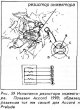
1. Turn the ignition key to the "OFF" position. 2. Disconnect the wiring harness from each injector. 3. Measure the resistance between the two injector terminals. The correct resistance for all is 1.5-2.5 ohms. Any...
1. Turn the ignition key to the "OFF" position. 2. Disconnect the wiring harness from each injector. 3. Measure the resistance between the two injector terminals. The correct resistance for all is 1.5-2.5 ohms. Any...
Injector resistor — check
1. With the ignition in the "OFF" position, disconnect the harness connector from the resistor. 2. Measure the resistance between terminal A of the resistor connector and the other terminal of the connector. When...
1. With the ignition in the "OFF" position, disconnect the harness connector from the resistor. 2. Measure the resistance between terminal A of the resistor connector and the other terminal of the connector. When...

Main Relay — Test
1. The simplest test of the main relay is that the engine starts and runs. If so, the main relay is functioning properly. 2. If you need to check the relay, remove it from under the dashboard and disconnect the harness...
1. The simplest test of the main relay is that the engine starts and runs. If so, the main relay is functioning properly. 2. If you need to check the relay, remove it from under the dashboard and disconnect the harness...
The «Check engine» indicator
The "CHECK ENGINE" lamp on the instrument cluster is checked by the ECU every time the ignition key is turned to the "ON" position. The lamp should light for 2 seconds and then go out. In a normal situation, the lamp...
The "CHECK ENGINE" lamp on the instrument cluster is checked by the ECU every time the ignition key is turned to the "ON" position. The lamp should light for 2 seconds and then go out. In a normal situation, the lamp...
This section is available on: russian, bulgarian, belarusian, ukrainian, serbian, croatian, romanian, polish, slovak, hungarian
Link in different formats to this section
TEXTHTMLBB Code
- General information
- Introduction to the guide
- User manual
- Maintenance
- Power unit
- Four-cylinder engines
- Six-cylinder engines
- Engine overhaul
- Cooling system
- Heater and air conditioner
- Power and exhaust systems
- Engine electrical equipment
- Engine management
- Transmission
- Mechanical gearbox
- Automatic gearbox
- Clutch and drive shafts
- Chassis and running gear
- Brake system
- Car suspension
- Steering
- Body and interior
- Exterior (external elements)
- Interior (internal elements)
- Electrical equipment
- Equipment and devices
- Electrical circuits
- General information
- Maintenance
- Power unit
- Engine adjustment
- Engine repair
- Engine electrics
- Emission management
- Engine management (carburetor)
- Electronic injection
- Programmable injection
- Schematic of emission system
- Fuel system
- Feedback management
- Transmission
- Manual gearbox
- Automatic gearbox
- Clutch
- Chassis and running gear
- Front suspension
- Rear suspension
- Steering
- Brake system
- Electrical equipment
- Ventilation and heating
- Air conditioner
- Cruise control system
- Equipment and devices