
Withdrawal
See figures 95 and 97.
1. Disconnect the wire from the negative battery terminal.
2. Rotate the engine to align the marks on the camshaft pulley and set cylinder #1 to TDC. Once the motor is in this position, it must not be rotated or moved.
3. Remove the mudguard from the bottom of the engine.
4. Disconnect the electrical connector from the cruise control actuator, then remove the actuator. Do not disconnect the cable; simply move the drive out of the work area.
5. Remove the power steering pump belt. Remove pump mounting bolts. Without disconnecting the hoses, move the pump out of the work area.
6. Disconnect the electrical wiring and connectors of the generator; remove the engine wiring harness from the valve cover.
7. Loosen the alternator and/or compressor adjusting and mounting bolts. Remove drive belt (And).
8. Remove the valve cover.
9. Remove the engine side support bracket, if equipped.
10. Remove the camshaft drive belt top cover.
11. Support the engine with a jack below the center of the center beam. Adjust the jack so that it only supports the beam, but does not lift it.
12. Remove the through bolt of the side engine mount and remove the mount.
13. Remove the oil dipstick and its tube.
14. Remove the adjusting nut.
15. Remove the crankshaft pulley bolt and the pulley itself.
This bolt is one of the tightest in the entire car. The pulley should be held in place while the bolt is loosened. Wrap the old drive belt around the pulley to keep it stable - don't try this with a belt that's on a car; it will stretch or break.
16. Remove the two rear bolts from the center beam. Slowly lower the jack and engine until there is more clearance to remove the lower camshaft belt cover.
17. Remove the lower camshaft drive belt cover.
18. There are two belts in this system; one going to the camshaft pulley is the camshaft drive belt. The other, shorter one controls the balance shaft and is called the baffle belt, or the timing belt. Pull the belt tensioner away from the belts to reduce tension. While holding the tensioner, install the adjusting nut and tighten it to hold the tensioner in place.
19. Carefully remove the balancer belt and camshaft drive belt. Do not twist or bend the straps; protect them from contact with oil or coolant. Remove belts from pulleys.
20. This is the right time to check or replace the water pump. Even if you only plan to replace the camshaft drive belt as part of a maintenance program, schedule a pump replacement at the same time.
For installation:
21. If the water pump must be replaced, install a new O-ring and position it correctly. Install water pump and fixing bolts. Tighten the fixing bolts to 12 Nm.
22. Check the position of the motor. The pointer on the back of the cylinder block must be exactly aligned with the white mark on the flywheel; The camshaft pulley must be aligned so that the word UP is on top of the pulley and the marks on the edge of the pulley are aligned with the head surfaces. Additionally, the front surface of the balancer pulley has a mark that must be aligned with the mark on the oil pump housing. This pulley must be installed on "10 hours" in relation to the crankshaft pulley as viewed from the center of the crankshaft pulley.
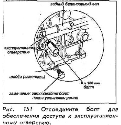
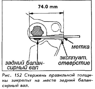
23. Align the rear balancer shaft pulley (on "2 hours", as viewed from the center of the crankshaft pulley), using a 6x100mm bolt or rod. Mark the bolt or rod 74mm from the end. Remove the bolt from the service hole on the side of the block; insert the rod into the hole. Set the 74 mm mark to be flush with the plane of the hole. This rod will hold the shaft in place during installation.
24. Place the camshaft drive belt over the pulleys and tensioners. Install the balance belt. Once the belts are in place, double check that all aligned engine parts are in the correct position. If not, remove the belts, re-mount the engine and install the belts. Once the belts are properly installed, slowly loosen and remove the adjusting nut, allowing the tensioner to move against the belts. Remove the rod from the operating hole and reinstall the bolt and washer.
25. Install the bottom cover by inserting the rubber grommets and positioning them correctly. Tighten the fixing bolts to 12 Nm.
26. Raise the lower beam and the engine into place. Install the bottom rear bolts (central) beams, tightening them to 39 Nm.
27. Install the key on the crankshaft and install the crankshaft pulley. Lubricate the threads of the bolts with oil and tighten them to 230 Nm.
28. Adjust the tension of the camshaft drive belt. Rotate the crankshaft counterclockwise until the camshaft pulley has rotated 3 teeth; this will put tension on the camshaft drive belt. Install the adjusting nut and tighten it to 45 Nm.
29. Install the oil dipstick and tube.
30. Install the motor side mount. Tighten the mounting bolt, nut and through bolt to 55 Nm. Remove the jack from under the central beam.
31. Install the camshaft drive belt top cover.
32. Establish an arm of a lateral support of the engine if it acted in film.
33. Install the valve cover.
34. Install the compressor and/or alternator drive belt; adjust tension.
35. Distribute the wiring to the valve cover and connect the wiring to the generator.
36. Install the power steering pump by tightening the bolt to 45 Nm and install the belt.
37. Install the cruise control actuator. Connect the vacuum hose and electrical connector.
38. Double check all installed parts, paying particular attention to loose hoses or slack wires, loose nuts, poorly routed hoses or wires (too tight or rubbing) and tools left in the engine area.
39. Install the mudguard under the engine.
40. Connect the wire to the negative battery terminal.
41. Start the engine at idle. Check for any signs of leaks or any sound of belts rubbing or binding.