
Component arrangement
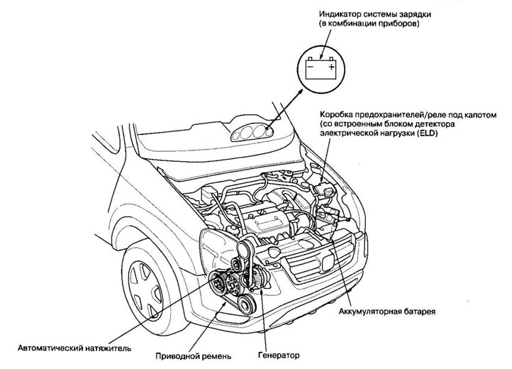
Troubleshooting the charging system
If the charging system indicator does not come on or go out, or the battery is discharged, test the following components in the order listed:
- Battery
- Charging system indicator
- Generator and regulator circuit
- Generator control system
Testing the charging system indicator
1. Turn the ignition key to the ON (II) position.
Does the charging system indicator light up?
Yes Proceed to p. 2.
No Proceed to p. 3.
2. Start the engine.
Does the charging system indicator go out?
Yes The charging system indicator is working properly.
No Proceed to p. 3.
3. Turn the ignition key to the OFF position.
4. Troubleshoot the multiplex control system.
Is the multiplex control system working properly?
Yes Without navigation system. Proceed to p. 7.
Yes With navigation system. Proceed to p. 5.
No Perform a multiplex control system check according to the fault code.
5. Disconnect the 12-pin connector from the AVN unit.
6. Start the engine.
Does the charging system indicator go out?
Yes Make sure the contacts are seated tightly in the connectors. If they are OK, install a known good AVN unit and retest.
No Proceed to p. 7.
7. Disconnect the 6-pin engine wiring harness connector from the 6-pin starter intermediate harness connector.
8. Measure the voltage at terminal #3 of the 6-pin engine wiring harness connector with the ignition switch in the ON (III) position.
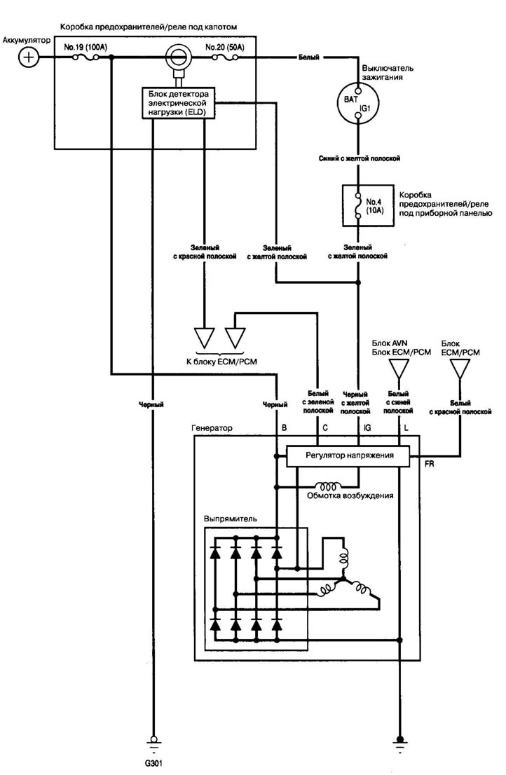
Electrical diagram
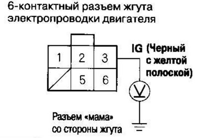
Is there battery voltage?
Yes Proceed to p. 9.
No Check to see if fuse #4 (10A) in the under-dash fuse/relay box is blown. If the fuse is good, repair the open circuit in the wire between the alternator and the under-dash fuse/relay box.
9. Turn the ignition key to the OFF position.
10. Disconnect the cable from the negative battery terminal.
11. Disconnect 24-pin connector B from the ECM/PCM.
12. Check for continuity between terminal B10 of the ECM/PCM connector and terminal No. 6 of the 6-pin engine wiring harness connector.
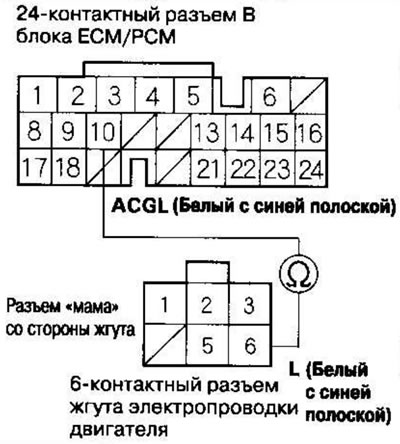
Is there conductivity?
Yes Proceed to p. 13.
No Repair open circuit in wire between alternator and ECM/PCM.
13. Check for continuity between ECM/PCM connector terminal B10 and ground.
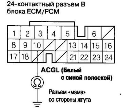
Is there conductivity?
Yes Repair short circuit in wire between generator and ECM/PCM.
No Connect the cable to the negative battery terminal and proceed to testing the generator and regulator.
Testing the Generator and Regulator Circuit
1. Make sure the battery is sufficiently charged and in good condition.
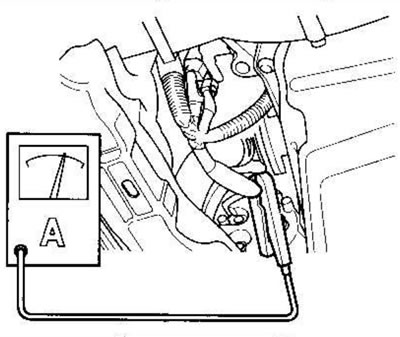
2. Connect an ammeter with a measurement range of 0-400 A to the starter intermediate harness.
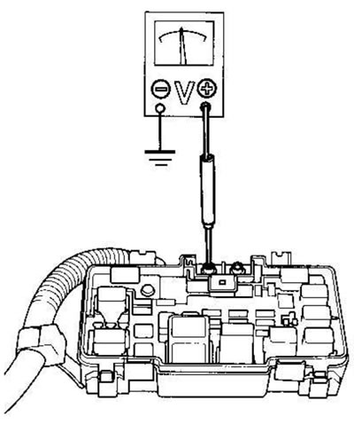
3. Connect a voltmeter with a measurement range of 0-20 A (with measurement accuracy up to 0.1 V) to terminal T101.
4. Start the engine. Maintain the engine speed at 3000 rpm (min1) with no electrical load, with the selector lever in position P or N, until the radiator fan comes on, then let it idle.
5. Increase the speed to 2000 rpm (min'1) and maintain it at this level.
6. Turn on the headlights (high beam) and measure the voltage at the contact in the fuse/relay box under the hood.
Voltage between 13.9 and 15.1 V?
Yes Proceed to p. 7.
No Repair or replace the generator.
7. Calculate the current at a voltage of 13.5 V.
Note: Adjust the voltage by turning on the fan, rear window defogger, brake lights, etc.
Current strength 60 A or more?
Yes The generator/regulator is working properly.
No Repair or replace the generator.
Testing the Generator Control System
1. Using the Malfunction Indicator Lamp (MIL), check to see if the Electrical Load Detector (ELD) unit is operating properly.
2. Disconnect the 6-pin engine wiring harness connector from the 6-pin starter intermediate harness connector.
3. Start the engine and turn on the headlights (high beam).
4. Measure the voltage between terminal #2 of the 6-pin engine wiring harness connector and the positive battery terminal.
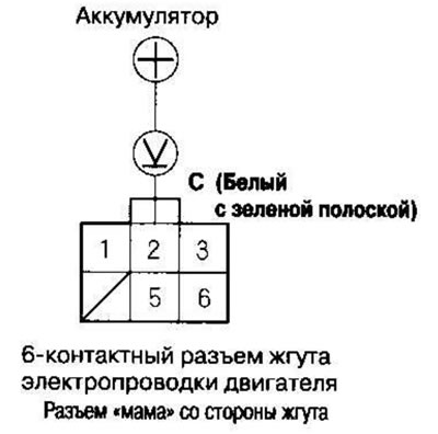
Voltage 1V or less?
Yes Proceed to p. 9.
No Proceed to p. 5.
5. Turn off the headlights and turn the ignition key to the OFF position
6. Disconnect the cable from the negative battery terminal.
7. Disconnect the 24-pin connector B from the ECM/PCM.
8. Check for continuity between ECM/PCM connector terminal B18 and ground.
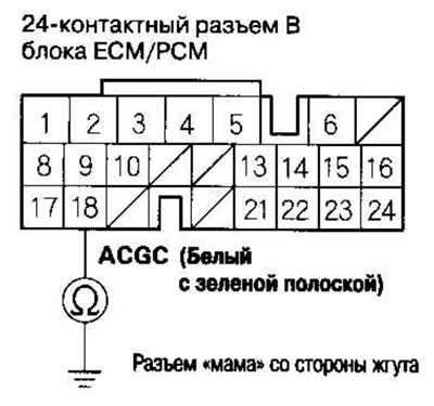
Is there conductivity?
Yes Repair short circuit in wire between generator and ECM/PCM.
No Make sure the contacts are seated tightly in the connectors. If they are OK, install a known good ECM/PCM and retest. If the required voltage is now present, replace the original ECM/PCM.
9. Turn off the headlights and turn the ignition key to the OFF position.
10. Disconnect the cable from the negative battery terminal.
11. Disconnect 24-pin connector B from the ECM/PCM.
12. Check for continuity between terminal B18 of the ECM/PCM connector and terminal No. 2 of the 6-pin engine wiring harness connector.
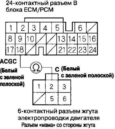
Is there conductivity?
Yes Repair or replace the generator
No Repair open circuit in wire between alternator and ECM/PCM.