
Disassembly/assembly
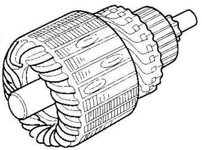
Rotor inspection and testing
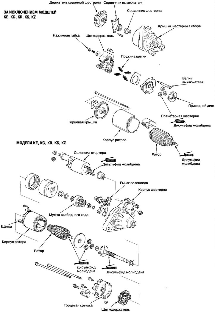
1. Remove the starter.
2. Disassemble the starter as described at the beginning of this procedure.
3. Check the rotor for wear or damage due to contact with the permanent magnet. Replace the rotor if necessary.
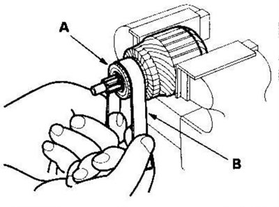
4. Check the surface of the commutator (A). If the surface is dirty or scorched, sand it or lathe it within the specified tolerances, or restore it with #500 or #600 sandpaper (B).
5. Check the commutator diameter. If the diameter is less than the limit, replace the rotor.
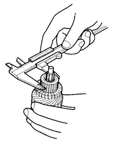
Commutator diameter
Except for models KE, KG, KR, KS, KZ
| Standard (new) | 28,028,1 mm |
| Wear limit | 27.5 mm |
Models KE, KG, KR, KS, KZ
| Standard (new) | 28.0 mm |
| Wear limit | 27.0 mm |
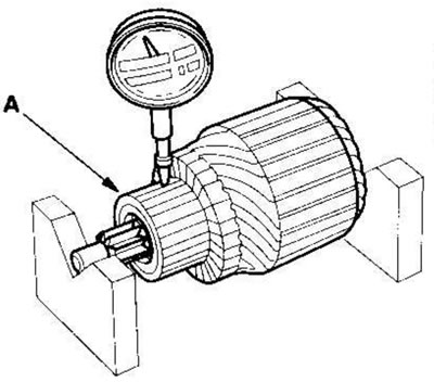
6. Measure the commutator runout (A).
- If the commutator runout is within tolerance, check for carbon dust or brass chips between the lamellas.
- If the commutator runout is greater than normal, replace the rotor.
Commutator beating
| Standard (new) | max 0.02 mm |
| Wear limit | 0.05 mm |
7. Check the depth of the mica recess (A). If the recess is small (B), cut the mica with a hacksaw blade and bring the depth to the standard. Cut out all the mica (C) between the commutator lamellas. The neckline should not be too shallow, too narrow or V-shaped (D).
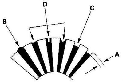
Commutator Mica Recess Depth
Except for models KE, KG, KR, KS, KZ
| Standard (new) | 0.40-0.50 mm |
| Wear limit | 0.15 mm |
Models KE, KG, KR, KS, KZ
| Standard (new) | 0.50-0.80 mm |
| Wear limit | 0.20 mm |
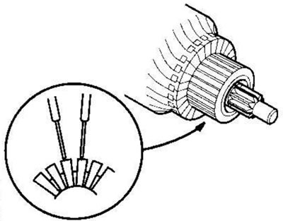
8. Check if there is conductivity between the commutator lamellas. If there is a break in the chain between any of the lamellas, replace the rotor.
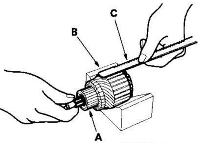
9. Place the rotor (A) on the stand (B). Bring the hacksaw blade (C) to the rotor core. If the web is attracted to the core or vibrates when the core rotates, the rotor is shorted. Replace the rotor.
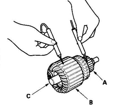
10. Using an ohmmeter, make sure that there is no continuity between the commutator (A) and the rotor coil core (B) and between the commutator and the rotor shaft (C). If there is conductivity, replace the rotor.
Checking the stator brushes
11. Measure the length of the brushes. If it is less than the tolerance, replace the brush holder assembly.
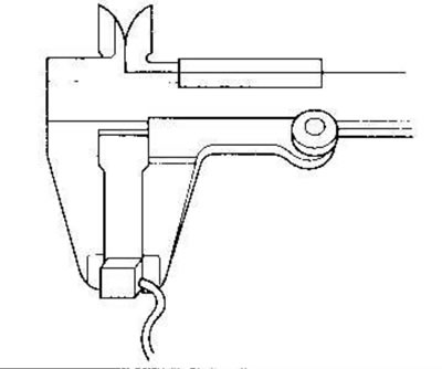
Length of brushes
Except for models KE, KG, KR, KS, KZ
| Standard (new) | 11.1-11.5 mm |
| Wear limit | 4.3 mm |
Models KE, KG, KR, KS, KZ
| Standard (new) | 14.0-14.5 mm |
| Wear limit | 9.0 mm |
Testing the stator excitation winding
Models KE, KG, KR, KS, KZ
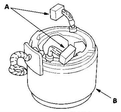
12. Check if there is continuity between the brushes (A). If there is no continuity, replace the rotor housing (B).
13. Check if there is continuity between each brush (A) and the rotor housing (B). If there is continuity, replace the rotor housing.
Testing the starter brush holder
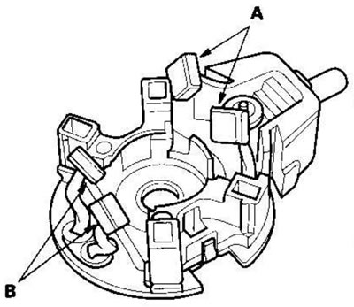
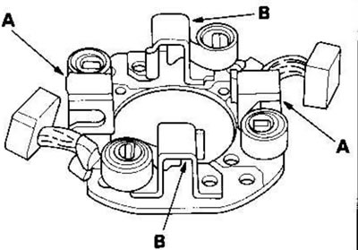
14. Make sure there is no conductivity between the positive (A) and negative (B) brush holders. If there is conductivity, replace the brush holder assembly.
Except for models KE, KG, KR, KS, KZ
Models KE, KG, KR, KS, KZ
Checking the brush springs
(Models KE, KG, KR, KS, KZ)
15. Insert the brush (A) into the holder and move the brush towards the commutator, then hook the spring balance (B) onto the spring (C). Measure the tension of the spring when the spring lifts the brush. If the spring tension is out of tolerance, replace the spring.
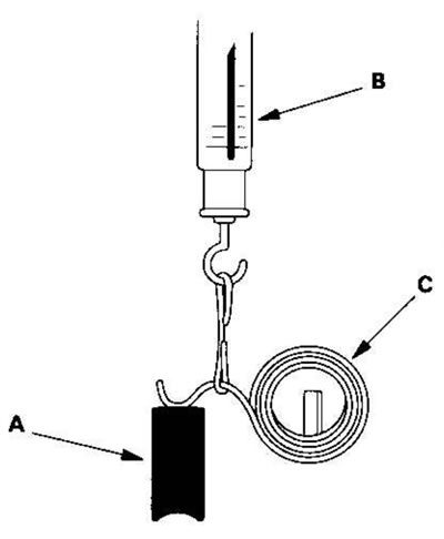
Spring tension: 13.7-17.7 N (1.40-1.80 kgf)
Checking planetary gears
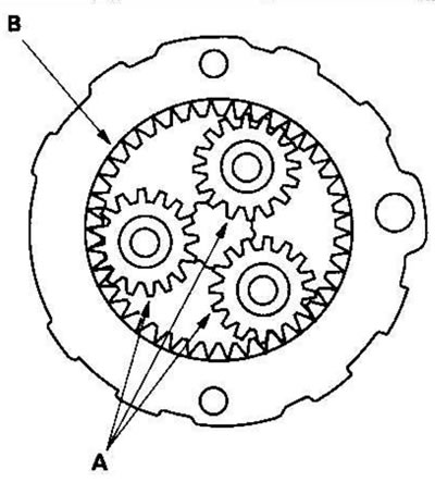
16. Check the planetary gears (A) and ring gear (B). If they are worn or damaged, replace them.
Checking the freewheel clutch
Except for models KE, KG, KR, KS.KZ
17. While holding the drive gear (A), rotate the gear shaft (B) clockwise. Make sure the pinion gear reaches the other end. If the pinion gear does not move smoothly, replace the pinion gear cover assembly.
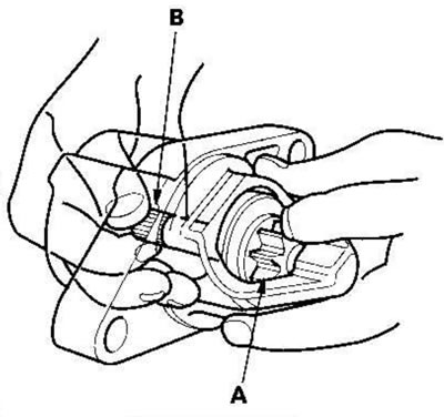
18. While holding the drive gear, rotate the gear shaft counterclockwise. The gear shaft should rotate freely. If the pinion gear does not rotate smoothly, replace the pinion gear cover assembly.
19. If the starter pinion is worn or damaged, replace the overrunning clutch assembly; the gear is not supplied separately. Check the condition of the flywheel or torque converter ring gear. If the starter pinion teeth are damaged, replace it.
Checking the freewheel clutch
Models KE, KG, KR, KS, KZ
20. Move the freewheel clutch on the shaft. If it does not move smoothly, replace it.
21. Turn the freewheel (A) in both directions. Does it lock in one direction and spin smoothly in the opposite direction? If it does not lock in either direction, or locks in both directions, replace it.
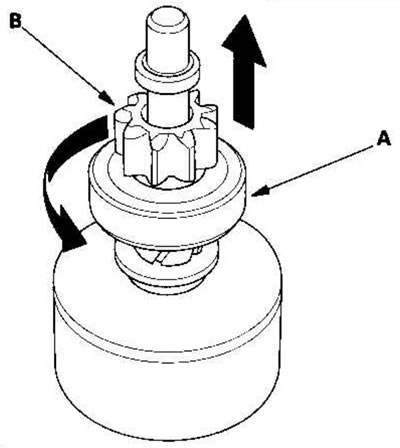
22. If the starter pinion gear (B) is worn or damaged, replace the overrunning clutch assembly; the gear is not supplied separately.
Check the condition of the flywheel ring gear. If the starter pinion teeth are damaged, replace it.
Assembling the starter
Except for models KE, KG, KR, KS, KZ
23. Place the brushes in the brush holder and insert the rotor (A) into the brush holder (B).
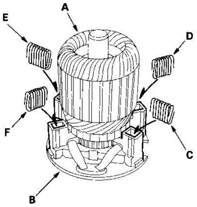
Note: To help the new brushes fit into place after they are installed in the holders, wrap a strip of #500 or #600 sandpaper with the rough side facing out around the commutator and rotate the rotor gently. In this case, the contact surface of the brushes is ground to match the contours of the commutator.
24. Compress the spring (C), insert it into the hole in the brush holder and press it until it touches the bottom. Repeat the operation for the other three springs (D, E and F).
25. Insert the rotor and brush holder into the housing.
Note: Make sure the rotor remains in the holder.
Models KE, KG, KR, KS, KZ
26. Pry up the brush springs with a screwdriver, then pull the brushes out of the holders approximately halfway and release the springs so that the brushes are fixed in this position.
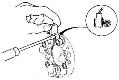
Note: To help the new brushes fit into place after they are installed in the holders, wrap a strip of #500 or #600 sandpaper with the rough side facing out around the commutator and rotate the rotor gently. In this case, the contact surface of the brushes is ground to match the contours of the commutator.
27. Insert the rotor into the housing and install the brush holder. Then pry up the brush springs again and push the brushes in until they snap into place against the commutator, then release the springs against the ends of the brushes.
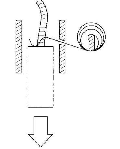
28. Install the starter end cover onto the brush holder.
(The original text of the article is located on the website hondabook.ru)