
1. Disconnect the 14-pin connector from the control unit.
2. Check the connector and contacts to ensure they are making proper contact.
- If contacts are bent, loose, or corroded, correct the problem and retest the system.
- If the contacts are OK, proceed to step. 3.
3. After disconnecting the 14-pin connector, perform a test at the input of the unit.
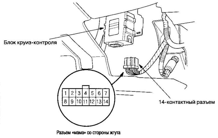
| Contact | Wire | Test condition | Test: required result | Probable cause if result is not achieved |
| 1 | Brown with white stripe | Apply power from the battery | Check the operation of the magnetic clutch: The clutch should make a clicking sound and the actuator should be locked. | The drive is faulty Poor grounding(G201) Wire break Short circuit to ground |
| 2 | Blue | Turn the ignition key to the ON (II) position, the main switch to the ON position, depress the brake pedal, then release | Check the voltage to ground: When the pedal is pressed, there should be 0 V, and when released, the battery voltage. | The brake pedal position switch is faulty Wire break Open circuit in cruise control main switch Fuse #4 (10A) in under-dash fuse/relay box blown |
| 3 | Black | Under all conditions | Check if there is conductivity to ground: There should be conductivity. | Poor grounding (G201) Wire break |
| 4 | Green with yellow stripe | Turn the ignition key to the ON (II) position | Check voltage to ground: Should be battery voltage | Fuse #4 (10A) in under-dash fuse/relay box blown Wire break |
| 5 | White with black stripe | Press the brake pedal and then release it | Check the voltage to ground: When the pedal is pressed, there should be battery voltage, and when released, 0 V | Fuse #7 (15A) in the under hood fuse/relay box has blown The brake pedal position switch is faulty Wire break |
| 6 | Gray with red stripe | Click on the Set button | Check voltage to ground: There should be battery voltage. When testing contact #6, there should be no voltage on contact #7. | Fuse #7 (15A) in the under hood fuse/relay box has blown The horn relay is faulty The SET/RESUME/CANCEL switch is faulty The twisted cable is faulty Wire break |
| 7 | Light green with black stripe | Click on the Resume button | Check voltage to ground: There should be battery voltage. When testing contact #7, there should be no voltage on contact #6. | |
| 9 | Brown | Apply power from the battery to brown contact, and grounding is on brown contact with a yellow stripe | Check the operation of the drive motor: You should hear the noise of the motor | The drive is faulty Wire break |
| 11 | Brown with yellow stripe | |||
| 10 | Blue with yellow stripe | Turn the ignition key to the ON (II) position | Short to ground: Cruise control indicator should light up in instrument cluster | Fuse #10 (7.5A) in under-dash fuse/relay box blown The instrument cluster is faulty Wire break |
| 12 | Blue with white stripe | Turn the ignition key to the ON (II) position, the main switch to the ON position; lift the front of the car and slowly rotate one wheel while holding the other | Check the voltage between blue contact with a white stripe (+) andblack contact (-): Should be 0-5 V or more multiple times. | The ECM/PCM is faulty Wire break Short circuit to ground |
| 13 | Light green | Turn the ignition key to the ON (II) position, the main switch to the ON position | Check voltage to ground: There should be battery voltage. | Fuse #4 (10A) in under-dash fuse/relay box blown The main switch is faulty Wire break |
| 14 | White with green stripe (automatic transmission) Blue (manual transmission) | Automatic transmission: Shift the selector lever to position [D] or [D3] Manual transmission: Release the clutch pedal | Check if there is conductivity to ground: There should be conductivity. Note: There should be no conductivity when pressing the clutch pedal or moving the selector lever to other positions. | The gearbox range switch is faulty The clutch pedal position switch is faulty Poor grounding (Manual transmission: G501, Automatic transmission: G101) Wire break |
| 8 | Blue with orange stripe | Connect the 14-pin connector to the cruise control unit, turn the main switch to the ON position and drive the vehicle at a speed greater than 40 km/h with the cruise control on. | Check the voltage to ground: There should be a voltage of about 1 V | Loose connection to the PCM block The cruise control unit is faulty Short circuit to ground |
4. If any test indicates a problem, identify and correct the cause, then retest. If all tests on the input of the unit pass, the control unit may be faulty. Install a known good control unit and retest. If the system is working properly, replace the control unit.