
Contents: Component arrangement ⇊ Troubleshooting the Starter Circuit ⇊ Testing the starter solenoid ⇊ Checking the starter operation ⇊ Electrical diagram ⇊
Component arrangement
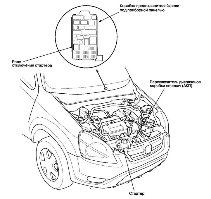
Troubleshooting the Starter Circuit
Note:
- During this procedure, the ambient temperature should be between 15 - 38°C.
- After performing this test or subsequent repair, reset the engine control module (ECM)/powertrain control module (PCM) to clear the fault codes from memory.
- The battery must be in good condition and fully charged.
Recommended procedure
- Use a starting system tester.
- Connect and operate the equipment in accordance with the manufacturer's instructions.
Procedure option
1. Connect the following equipment:
- Ammeter, 0-400 A
- Voltmeter, 0-20 V (with measurement accuracy up to 0.1 V)
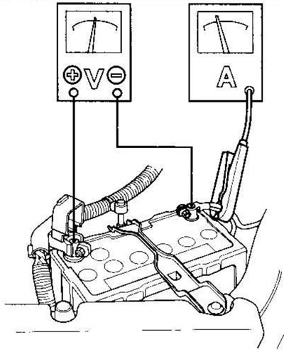
- Tachometer, 0-1200 rpm (min')
2. Remove fuse #6 (15A) from the underhood fuse/relay box.
3. Turn the ignition key to the START (III) position, with the selector lever in position [N] or [P] (automatic transmission).
Did the starter turn the engine normally?
Yes The starting system is in good working order.
No If the starter does not turn the engine at all, proceed to step. 4. If the engine cranks erratically or too slowly, proceed to step. 7. If it does not disengage from the flywheel or torque converter ring gear when the key is released, check the following until you find the cause.
- Is there any malfunction in the solenoid core and switch?
- Is the drive gear dirty or is the overrunning clutch damaged?
4. Check the battery status. Check the battery electrical connections, negative battery cable ground connection, engine ground cables and starter for loose connections and corrosion. Then try starting the engine again.
Did the starter turn the engine?
Yes After fixing the loose connections, the problem disappeared. The starting system is in good working order.
No Proceed to p. 5.
5. Make sure the transmission is in neutral, then disconnect the black wire with white stripe (A) from the starter solenoid (B). Connect a jumper wire between the positive battery terminal and the solenoid terminal.
Except for models KE, KG, KR,KS, KZ
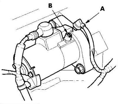
Models KE, KG, KR, KS, KZ
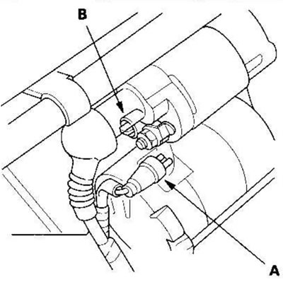
Did the starter turn the engine?
Yes Proceed to p. 5.
No Remove the starter and have it repaired or replaced.
6. Check the following components in the order shown until you find an open circuit:
- Check the black wire with white stripe and the connections between the under-dash fuse/relay box and the ignition switch and between the under-dash fuse/relay box and the starter.
- Check the ignition switch.
- Check the range switch and the transmission connector (automatic transmission).
- Check the starter cut-off relay (automatic transmission).
7. Check the engine speed when cranking.
Engine speed above 100 rpm (rpm)?
Yes Proceed to p. 8.
No Replace the starter or remove and disassemble it and check the following until you find the cause.
- Are there excessive wear on the starter brushes?
- Is there a break in the rotor lamellas?
- Are the helical splines or pinion gear dirty or damaged?
- Are there any defects on the drive pinion clutch?
8. Check the cranking voltage and current consumption.
Cranking voltage is greater than or equal to 8.5 V (except for models KE, KG, KR, KS, KZ)/8,7 V (models KE, KG, KR, KS, KZ), and the consumed current is less than or equal to 350 A (K20A4 motors (except for models KE, KG, KR, KS, KZ), K20A5)/380 A (k24A1 engines)/230 A (K20A4 engines (models KE, KG, KR, KS, KZ)?
Yes Proceed to p. 9.
No Replace the starter or remove and disassemble it and check the following until you find the cause.
- Is there a break in the starter rotor lamellas?.
- Is the starter rotor seizing?.
- Is there a short circuit in the rotor winding?.
- There is no excessive resistance caused by friction in the engine.
9. Remove the starter and check the starter pinion and flywheel or torque converter ring gear for damage. Replace damaged components.
Testing the starter solenoid
Models KE, KG, KR, KS, KZ
1. Check the holding coil for continuity between terminal S (A) and the rotor housing (ground). There should be continuity.
- If there is conductivity, proceed to step. 2.
- If there is no continuity, replace the solenoid.
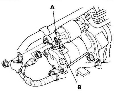
2. Check the pull-in coil for continuity between terminals S (A) and M (B). There should be continuity.
- If there is conductivity, the solenoid is good.
- If there is no continuity, replace the solenoid.
Checking the starter operation
Except for models KE, KG, KJ, KS, KZ
1. Disconnect the wire from terminal S (A).
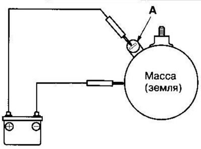
2. Make connections as shown below using wire with a cross-section similar to or equivalent to that used on the vehicle. To avoid damaging the starter, do not apply power from the battery for more than 10 seconds.
3. Connect the battery as shown in the figure. If the starter pinion extends, the starter is working properly.
4. Disconnect the battery from ground. If the starter pinion retracts immediately, the starter is working properly.
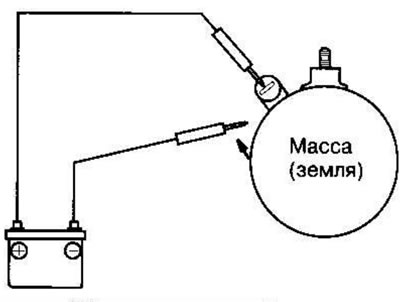
5. Secure the starter in a vice.
6. Connect the starter to the battery as shown in the diagram below and check that the engine starts and continues to turn.

7. If the current and speed of the electric motor correspond to the nominal values at a battery voltage of 11.5 V, the starter is working properly.
Specifications:
| Current | 80 A or less | |
| Electric motor speed | Engines K20A4, K20A5 | 2500 rpm (min*1) or more |
| Engine K24A1 | 2300 rpm (min1) or more | |
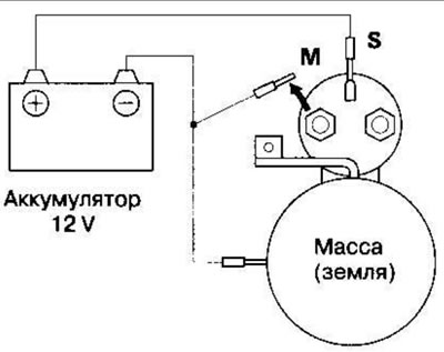
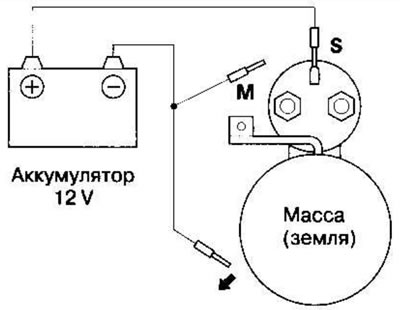
Models KE, KG, KR, KS, KZ
1. Disconnect the wires from terminals S and M.
2. Make connections as shown below using wire with a cross-section close to or equivalent to
the one used on the car. To avoid damaging the starter, do not apply power from the battery for more than 10 seconds.
3. Connect the battery as shown in the figure. If the starter pinion extends, the starter is working properly.
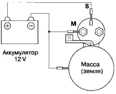
4. Disconnect the battery from the M terminal. If the starter pinion does not retract, the holding coil is working properly.
5. Disconnect the battery from ground. If the starter pinion retracts immediately, the starter is working properly.
6. Secure the starter in a vice.
7. Connect the starter to the battery as shown in the diagram below and check that the engine starts and continues to turn.

8. If, at a battery voltage of 11.5 V, the current and speed of the electric motor correspond to the nominal values, the starter is working properly.
Specifications:
| Current | 90 A or less |
| Speed of rotation | 3000 rpm (min⁻¹) |
| electric motor | or more |
Electrical diagram
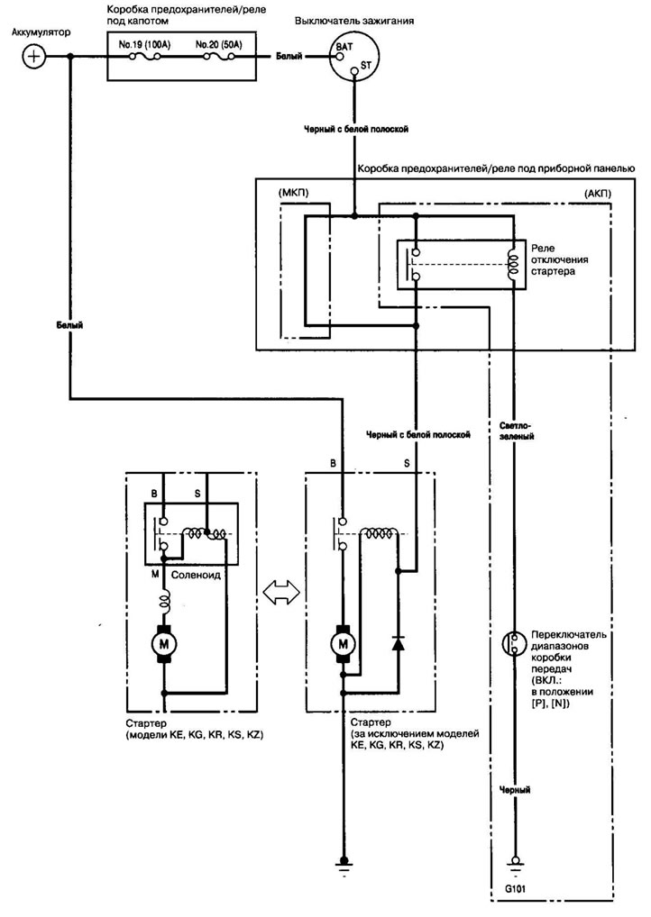
The original is located on the website Hondabook.ru