
Note: If necessary, the clearance between the push rod and the master cylinder piston should be checked and adjusted before installing the master cylinder.
1. Attach the special tool (A) to the master cylinder body (B); by turning the adjusting nut (F), move the central axis (C) until its upper part (D) rests against the end of the secondary piston (E).
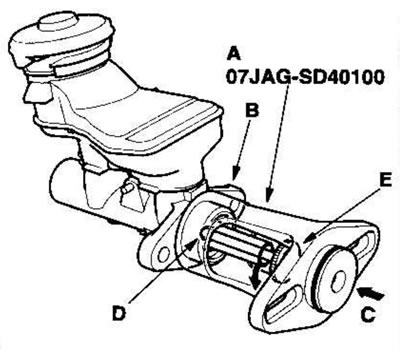
2. Without disturbing the position of the central axis, fix the special tool (A) upside down on the amplifier.
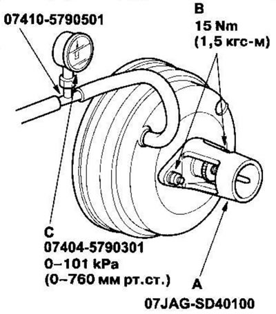
3. Install nuts (B) on the master cylinder and tighten to the specified torque.
4. Connect a vacuum gauge (C) with a measuring range of 0-101 kPa in series (0-760 mmHg.) to the engine vacuum source in the booster and maintain engine speed to provide a vacuum of 66 kPa (500 mmHg.).
5. Using the feeler gauge (A), measure the gap between the tool body and the adjusting nut (B) as shown in the figure.
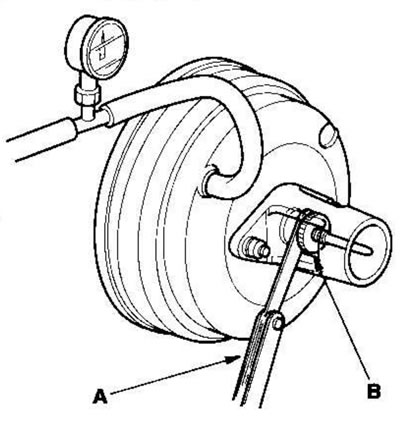
If the clearance between the fixture body and the adjusting nut is 0.4 mm, the clearance between the push rod and the piston is 0 mm. However, if the clearance between the fixture body and the adjusting nut is 0 mm, the clearance between the push rod and the piston is 0.4 mm or more. Therefore, it should be adjusted and rechecked.
Clearance: 0-0.4 mm
6. If the clearance is different from the standard, loosen the star lock nut (A) and adjust by turning the adjuster (B) in or out.
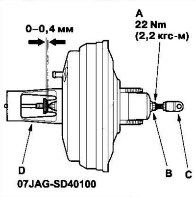
- Make adjustments when applying the required vacuum to the booster.
- When making adjustments, secure the pin (C) with a head and a hole for a cotter pin.
7. Tighten the star lock nut securely.
8. Remove the special tool (D).
9. If the booster is removed, adjust the length of the push rod (A) as shown in the figure. If the length is different from the standard, loosen the push rod lock nut (B) and adjust by screwing in or out the pin (C) with a head and a hole for a cotter pin.
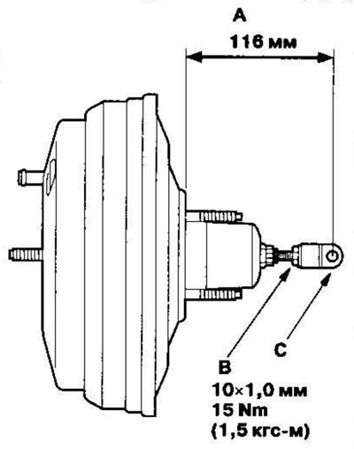
10. Install the master cylinder.