
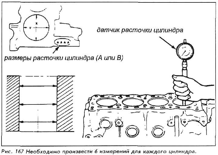
2. If the taper and ovality of the cylinder liner is within specification and there are no nicks or scratches on the walls, then no boring is required. If this is not the case, then the cylinder must be bored to a larger size to eliminate taper and ellipse. In this case, the block must be taken to a workshop for precision machining by a qualified mechanic using specialized equipment.
If you are boring the cylinder, then be sure to install larger pistons and rings. Since all pistons must be the same size, it is necessary to bore all cylinders, even if the dimensions of only one of them are outside the tabular data.
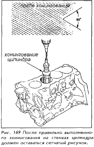
3. Even if the cylinders do not need to be bored, they still need to be honed. To remove the gloss on the walls of the cylinder, you can use the polishing nozzle for a conventional drill.
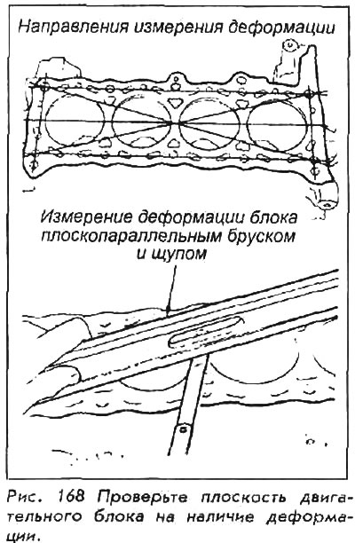
4. Head top (the surface where the gasket is placed) should be examined for deformation. Run a straight edge along all four edges of the block, diagonally through the center. If you can pass a 0.1mm feeler gauge under the ruler, the top surface of the block should be machined or straightened.
5. Remove the rings from the piston using a piston ring remover. Save all rings and the piston they were removed from. The rings and grooves in the piston must be completely cleaned with a brush and solvent, as deposits will prevent proper ring wear measurements.
6. Before starting all measurements, inspect the piston (need a magnifying glass) for any signs of cracking, especially in the skirt area. Anything more severe than light scratches on the surface means the piston is no longer fit for further use. The metal will heat up unevenly and the piston may break, especially while the engine is running. If there is a very loud noise - do not risk it, as this is fraught with very expensive repairs.
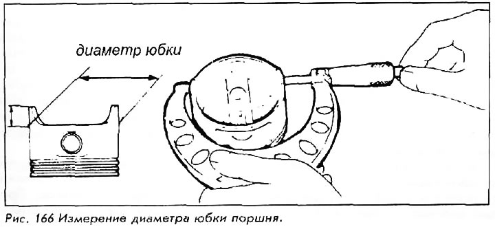
7. Piston diameter is measured at the piston skirt, at right angles to the piston pin.
Compare the measurement or with the diameter shown in the table, or subtract the piston diameter from the bore size of the cylinder to obtain the clearance value. If the clearance is excessive, the piston must be replaced. If the gap when installing a new piston is still not within the table data, select a larger piston and bore the cylinders accordingly.
8. Compression ring backlash is measured after the cleaned rings are placed using a piston ring remover back into their original positions on the piston. Measure the clearance while trying to advance the template (with thickness within tabular specification) between the ring and the edge of the annular groove. If the template does not fit into the groove, the ring can be used, although it is always recommended to use new rings. If this template will pass, and the template with a greater thickness equal to the wear limit will not, then the piston can still be used, but new rings must be installed.
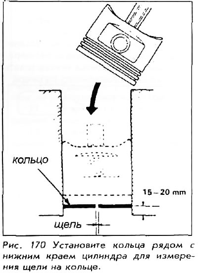
9. It is necessary to measure the annular gaps for all three rings, placing the piston with the rings in its cylinder, but with the reverse side (top down). The rings must be at least 1520 mm from the base of the cylinder. Use the template to measure the annular gaps and compare the measurement values with the table values. If the gap is too large, the ring should be checked with a gauge with a thickness equal to the wear limit. If there is little wear on the cylinder liner, you can use new rings to bring the ring gaps to specification without reboring the cylinder itself. Measure gaps by placing the ring near the bottom of the cylinder, not near the top where wear is greatest.
10. Connecting rods must not be worn, split or bent. Examine them, especially at the top and bottom. Pay attention to any sign of metal deformation or wear. The piston pin must sit clean and secure. Threaded through the upper end of the connecting rod, it should not stagger or roll. The lower end of the connecting rod must also be in the form of an exact semicircle without deformation.