
Accord 1990-91
Steps are given to remove the crankshaft without changing the position of the pistons in the cylinder block.
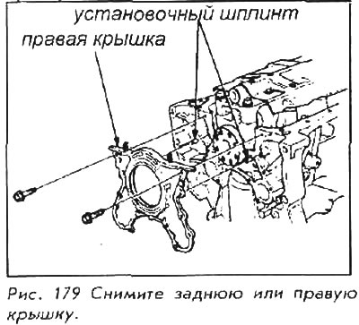
1. Remove the engine from the car, as well as the flywheel from the engine, unscrew the rear or side right cover from the engine.
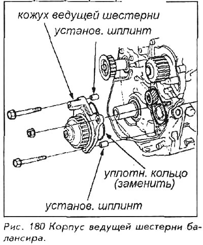
2. Remove the balancer drive cover.
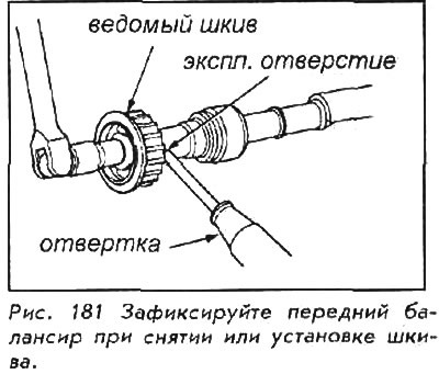
3. Insert a metal pin or similar tool into the front balance shaft service hole to hold it in place. Unscrew the belt sprocket and remove it.
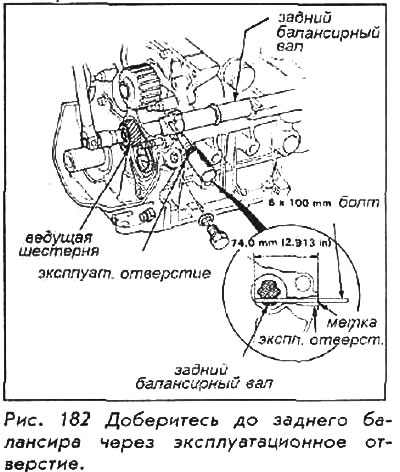
4. Remove the bolt from the rear balance shaft service hole. Align the bolt hole with the hole on the rear balancer shaft. Insert a 6x100mm pin or bolt to support the shaft; remove the drive gear or sprocket.
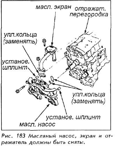
5. Remove the oil screen and oil pump. Remove the baffle.
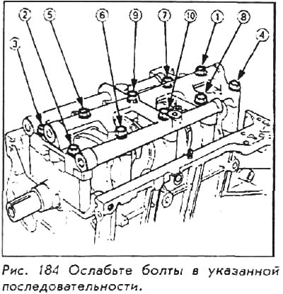
6. Remove the bolts and bridge of the bearing caps, then remove the caps themselves. Loosen the tightness by turning each bolt approximately 1/3 turn in one step, starting at one end, then moving to the diagonally opposite corner. Follow the sequence shown in the picture.
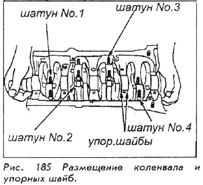
7. Turn the crankshaft so that the crankshaft journals No.2 and 3 are down. Remove the connecting rod caps and bearings, remember where each of them stood - this will come in handy during assembly.
8. Remove the crankshaft from the engine - do not damage the journals.
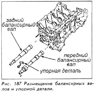
9. Remove the bolts and thrust parts, then remove the rear and front balancer shafts.
For installation:
10. Insert the bearing shells into the block and connecting rods.
11. Hold the crankshaft so that the piston journals No. 2 and 3 were strictly below; lower the crankshaft into the block. Make sure the crankshaft journals fit into No.2 and No.3 connecting rods.
12. Install the connecting rod caps and hand-tighten the nuts.
13. Rotate the crankshaft clockwise and place the journals on the No.1 and 4 piston connecting rods. Install the connecting rod caps and hand-tighten the nuts.
14. Check the clearances of the connecting rod bearings using a flattened measuring strip.
15. Coat the thrust washer and bolt threads with a light coat of clean oil. Install thrust washers, main bearing caps and bearing cap bridge. Check bearing clearances using a flattened measuring strip.
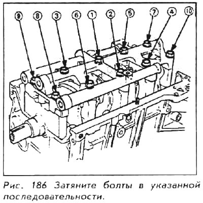
16. Tighten the bolts in two passes: On the first pass, in the correct sequence, tighten each bolt to approximately 30 Nm. On the second pass, in the correct sequence, tighten each bolt to the final tightening torque of 72 Nm.
17. Insert the balance shafts into the block, then install the thrust piece to the front balance shaft and block. Tighten the fixing bolt to 12 Nm.
18. The mating surfaces of the right cover and block must be absolutely clean and dry. Apply a liquid gasket to the contact surface of the cover, then install it on the block. Tighten the bolts to 12 Nm.
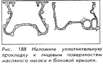
19. The mating surfaces of the oil pump and engine block must be absolutely clean and dry. Apply a liquid gasket to the contact surface of the oil pump. Lubricate the valve seals of the pump and balancer with grease. Install the oil pump and tighten the bolts to 12 Nm. Wipe excess grease from crankshaft and balance shaft; check that the seals are not deformed during installation.
20. Install baffle plate, then install oil screen.
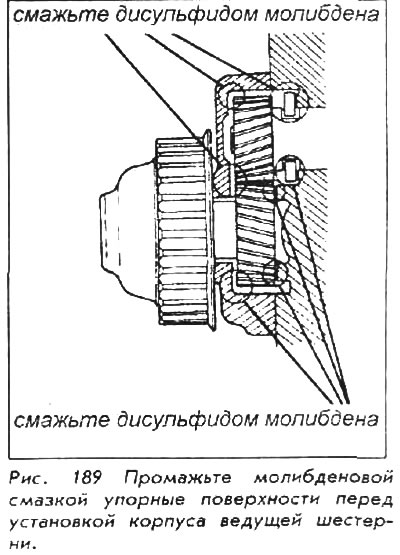
21. Apply molybdenum disulphide grease to the thrust surfaces of the balance gears before installing the driven gear and drive gear housing.
22. Use a 6x100mm tool to hold the rear balance shaft in place. Install balancer pulley and gear. Tighten the bolts to 25 Nm.
23. Fix the front balance shaft in place and install the pulley; tighten the bolts to 30 Nm.
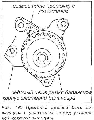
24. On the balancer drive housing, align the notch on the edge of the pulley with the index on the housing.
25. Hold the rear balance shaft in place and install the drive housing. Tighten nuts and bolts to 25 Nm.
Cleaning and checking the oil clearance of bearings
Remove bearing cap to inspect. Using a clean, dry rag, completely clean all oil from the crankshaft journal and bearing.
plastigage (Plastigage) or similar flattened meter are oil soluble.
Place a measuring strip along the entire width of the bearing shell and tighten to specification. Remove the bearing cap and determine the clearance by comparing the width of the flattened strip with the scale on the package. See Fig.165.
Do not turn the crankshaft while measuring the clearance.
Crankshaft axial clearance / connecting rod side clearance
Place a small piece of metal between the main bearing cap and the crankshaft casting without damaging any journal. Move it back and forth; Measure the distance between the thrust bearing and the crankshaft using a gauge. Compare measurements with specifications. If the clearance is too large, you will need to replace the main bearing with a wider working surface or replace the crankshaft. Consult the workshop about this.
The clearance between the bottom end of the connecting rod and the crankshaft casting can be checked with a feeler gauge. As far as possible, press the connecting rod to one side and measure the distance on the other side.