
The ends of the bearing shells must never be sawn flush with the surface of the mating parts of the connecting rod and cap.
If the connecting rod starts to make noise or it is so worn that its clearance on the crankshaft is increased, select and install a new bearing of the correct size. In this case, there is no other way to solve this problem. Under no circumstances should the end of the connecting rod or cap be ground to compensate for wear.
Inspect the connecting rod bearings at the same time as removing the connecting rods. If the earbuds are scratched or peeling, they must be replaced. ANY notch or bulge on the crankshaft means it needs to be replaced.
Bearings can be replaced only according to their standard sizes, usually marked on the liners or on the connecting rod cap. Do not confuse the brand on the bearing cap with the cylinder number. It is very possible that the No. 3 piston connecting rod contains the number 1, indicating the size code for the connecting rod bearing hole. The connecting rod cap may also have a number "1", embossed on it.
Measuring clearance between connecting rod bearing and crankshaft (oil clearance) carried out using a plastic measuring tool such as plasty-geych (Plasti-gage) or a similar product.
1. Remove the connecting rod cap along with the bearing. Completely clean the cover, liners and neck on the crankshaft. Blow the oil out of the oil hole on the crank. Plastic tools are oil soluble and will begin to fall apart if the area is not completely free of oil.
2. Place a measuring strip along the center of the base of the bottom liner. Install the cover, insert and tighten the bolts in three passes to the correct torque.
Do not turn the crankshaft after installing the measuring strip.
3. Remove the bearing cap with bushing. The flattened plastic gauge will stick to the liner or crankshaft journal. But don't take it off just yet.
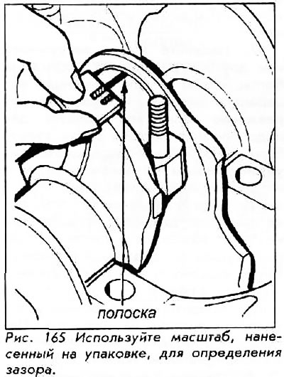
4. Use the scale printed on the gauge package to measure the width of the flattened gauge strip at its widest point. The nearest number within the scale for the measured width will indicate the gap in thousandths of an inch.
5. Refer to the clearance specification table in the middle of this chapter. If any measurement approaches the maximum allowable value, replace the bearing.
6. If the bearing is OK, remove the meter, lubricate the bearing surfaces completely and install it in the cover. Install the other half of the bearing into the end of the connecting rod and attach the cap to the connecting rod. Evenly, in three passes, tighten the nuts to the required torque.
7. If the bearing is installed correctly and the nuts are properly tightened, you can move the connecting rod back and slightly forward along the axis of the crankshaft. If the connecting rod does not move, this means that the bearing is too small or the connecting rod is overtightened.