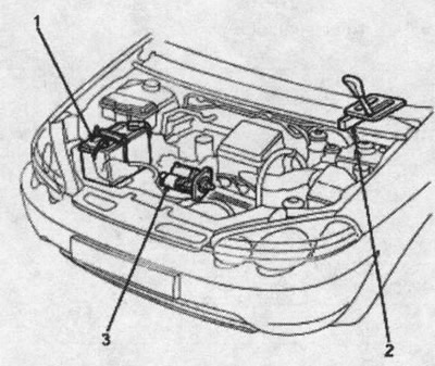
Launch System Component Locations
Note: Left hand drive model shown; the location on the right-hand drive model is similar.
1. Battery
2. Shift selector switch
3. Starter
Note: Before testing, the ambient temperature must be between 15 and 38°C.
Recommended procedure:
- Use a tester for the launch system.
- Connect and operate the equipment in accordance with the manufacturer's instructions.
- Perform testing and troubleshooting as described below.
Procedure option:
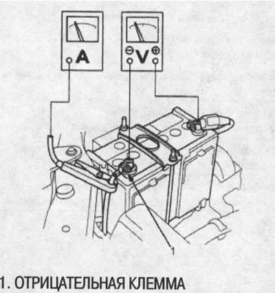
- Use the following equipment: o Ammeter, measuring range 0-400 A
- Voltmeter, measurement range 0-20 V (with measurement accuracy up to 0.1 V)
- Tachometer, measuring range 0-1200 rpm (min')
- Connect the voltmeter and ammeter as shown in the figure.
Note: After this test or subsequent repair, reset the ECM/PCM to clear any existing trouble codes.
Check starter engagement:
1. Remove fuse No. 59 (15 A) from the fuse/relay box under the hood.
2. Turn the ignition key to the START position (III) by setting the selector lever to position N or P. The starter should turn the engine over.
- If the starter does not crank the engine, go to step 3.
- If the engine cranks erratically or too slowly, go to step. «Check for wear and damage» below.
3. Check the battery, battery positive cable, ground, starter disable relay, and wire connections for looseness and corrosion. Repeat testing. If the starter still does not crank the engine, go to step 4.
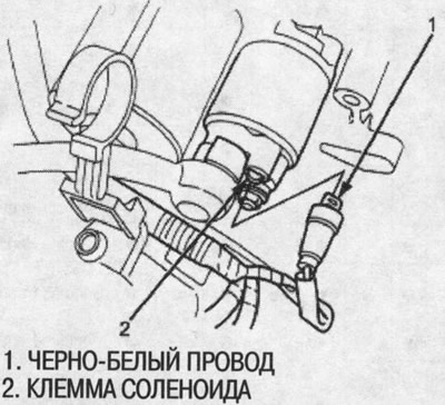
4. Disconnect the connector (BLACK/WHITE solenoid wire and terminal) from the starter.
5. Connect the positive (+) battery terminal and solenoid terminal with a jumper. The starter should turn the engine over.
If the starter still does not crank the engine, remove it and diagnose its internal problems.
If the starter cranks the engine, go to step 6.
6. Check ignition switch (see ch. «Body electrical equipment»).
7. Check Starter Disable Relay (see ch. «Body electrical equipment»).
8. Check immobilizer system (see ch. «Body electrical equipment»).
9. Check the automatic transmission selector switch (see ch. «Automatic gearbox»).
10. Check for an open in the wire between the ignition switch and the starter.
Check for wear and damage
The starter should turn the engine smoothly and steadily. If the starter engages but cranks the engine erratically, remove it and check for damage to the starter drive gear and torque converter ring gear.
Check the drive gear freewheel for binding or slipping when the starter rotor rotates with the drive gear. If there is damage, replace the gears.
Checking cranking voltage and current consumption
The cranking voltage must be at least 8.5 V. Current consumption - no more than 350 A.
If the cranking voltage is too low or the current draw is too high, check:
- is the battery dead
- is there a break in the starter rotor lamellas
- Is the starter rotor sticking?
- is there a short circuit in the rotor winding
- whether there is excessive resistance caused by friction in the motor
Checking the speed when cranking
Engine speed when cranking must be above 100 rpm (min-1).
If RPM is too low, check:
- Are the battery or starter terminals loose?
- Is there excessive wear on the starter brushes?
- is there a break in the rotor lamellas
- the spiral spline or pinion is not dirty or damaged
- whether there are any defects on the freewheel of the drive gear
Starter disengage test
With the selector lever in the N or P position, turn the ignition key to the START position (III) and release it to the ON position (II). When the key is released, the starter drive gear should disengage from the torque converter ring gear.
If the drive gear is stuck on the torque converter ring gear, check:
- whether there are any malfunctions in the operation of the core and the switch of the solenoid
- Is the pinion gear assembly dirty or freewheel damaged?
Starter Solenoid Test
1. Check holding coil for continuity between terminal S and rotor housing (earth). The coil is good if there is continuity.
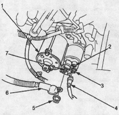
1. rotor housing (Earth); 2. terminal S; 3. terminals; 4. black and white wire; 5. fastening nut, terminal B, 9 Nm (0.9 kgf/m); 6. starter cable; 7. terminal B
2. Check the pull-in coil for continuity between terminals S and M. The coil is good if there is continuity.
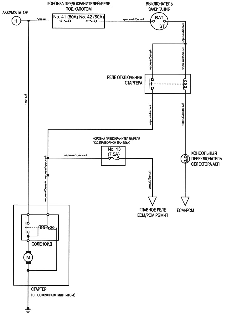
Wiring diagram (Left hand drive CVT)
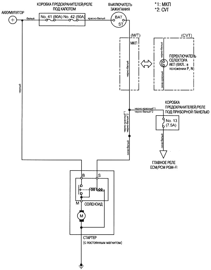
Wiring diagram (Manual, CVT RHD)