


Brake system of the car Honda Avancier 1


Frequency of checking rubber components and brake booster
A. Checking the operation of the brake booster Press the brake pedal and check the braking efficiency. If the efficiency is insufficient, check the operation of the brake booster and its tightness (see below). If the...
A. Checking the operation of the brake booster Press the brake pedal and check the braking efficiency. If the efficiency is insufficient, check the operation of the brake booster and its tightness (see below). If the...

Checking and adjusting the brake pedal
Pedal height Measure the distance from the pedal to the floor surface. Unscrew the notch in the insulator and measure the distance from the center of the left edge of the pedal to the metal surface of the floor. After...
Pedal height Measure the distance from the pedal to the floor surface. Unscrew the notch in the insulator and measure the distance from the center of the left edge of the pedal to the metal surface of the floor. After...

Checking and adjusting the parking brake pedal
Examination Press the parking brake pedal with a force of 294 N (30 kg) and check the pedal travel (count the number of clicks). Pedal travel: 5-7 clicks (when pressing the pedal with a force of 294 N (30 kg)) If the...
Examination Press the parking brake pedal with a force of 294 N (30 kg) and check the pedal travel (count the number of clicks). Pedal travel: 5-7 clicks (when pressing the pedal with a force of 294 N (30 kg)) If the...

Brake system — bleeding
Attention: Prevent foreign particles and water from entering the system when adding brake fluid. To prevent chemical changes in the brake fluid, do not mix different types of fluid. Use genuine Honda Ultra DOT 3 or DOT...
Attention: Prevent foreign particles and water from entering the system when adding brake fluid. To prevent chemical changes in the brake fluid, do not mix different types of fluid. Use genuine Honda Ultra DOT 3 or DOT...

Front Brake Pads — Checking and Replacing
Examination Check the thickness of the pads. If the thickness of the pads is less than the maximum, replace the inner and outer pads as a set. Standard pad thickness: 11 mm Maximum pad thickness: 1.6 mm Without taking...
Examination Check the thickness of the pads. If the thickness of the pads is less than the maximum, replace the inner and outer pads as a set. Standard pad thickness: 11 mm Maximum pad thickness: 1.6 mm Without taking...

Front brake discs — check for runout
When replacing the brake disc with a new one, check it for runout. 1. Securely fasten the brake disc with the wheel nuts. To avoid damaging the conical areas of the wheel nuts, use suitable flat washers. 2. Place the...
When replacing the brake disc with a new one, check it for runout. 1. Securely fasten the brake disc with the wheel nuts. To avoid damaging the conical areas of the wheel nuts, use suitable flat washers. 2. Place the...

Front brake discs — thickness and parallelism check
1. Check for cracks, excessive scoring and stepped wear due to wear on the friction surfaces of the disc. 2. Measure the thickness of the disc at a distance of 10 mm from its edge at 8 points with a step of...
1. Check for cracks, excessive scoring and stepped wear due to wear on the friction surfaces of the disc. 2. Measure the thickness of the disc at a distance of 10 mm from its edge at 8 points with a step of...

Front Brake Discs — Brake Disc Grinding
1. Perform grinding using a brake disc grinder. For sanding instructions, please refer to the instructions for your sanding machine. Grind the disc so that the disc thickness remains greater than the maximum. Maximum...
1. Perform grinding using a brake disc grinder. For sanding instructions, please refer to the instructions for your sanding machine. Grind the disc so that the disc thickness remains greater than the maximum. Maximum...

Front Brake Caliper — Disassembly
Attention. Make sure that brake fluid does not come into contact with paintwork. If the fluid does come into contact with paintwork, wash it off immediately with water. To prevent brake fluid from leaking from...
Attention. Make sure that brake fluid does not come into contact with paintwork. If the fluid does come into contact with paintwork, wash it off immediately with water. To prevent brake fluid from leaking from...

Front Brake Caliper — Assembly
Attention: Do not apply oil to the rubbing surfaces of the disc and pads. Be sure to replace non-reusable components with new ones. Prevent foreign particles from entering the cylinders and dust boots. Make sure that...
Attention: Do not apply oil to the rubbing surfaces of the disc and pads. Be sure to replace non-reusable components with new ones. Prevent foreign particles from entering the cylinders and dust boots. Make sure that...

Master Cylinder and Brake Booster — Removal and Installation
Attention: Make sure that brake fluid does not come into contact with paintwork. If the fluid does come into contact with paintwork, wash it off immediately with water. Do not damage or deform the brake pipes...
Attention: Make sure that brake fluid does not come into contact with paintwork. If the fluid does come into contact with paintwork, wash it off immediately with water. Do not damage or deform the brake pipes...

Disassembling the master cylinder
Attention: Replace unused components. Flush the removed components with brake fluid and blow out all ports with compressed air. Avoid allowing foreign particles to come into contact with the removed components. 1....
Attention: Replace unused components. Flush the removed components with brake fluid and blow out all ports with compressed air. Avoid allowing foreign particles to come into contact with the removed components. 1....

Assembling the master cylinder
Attention: If the primary, secondary pistons or master cylinder housing have been replaced, be sure to check and adjust the push rod clearance (see below). Be sure to replace unused components. Do not reuse drained...
Attention: If the primary, secondary pistons or master cylinder housing have been replaced, be sure to check and adjust the push rod clearance (see below). Be sure to replace unused components. Do not reuse drained...

Checking and adjusting the clearance of the push rod
This check is performed when replacing the master cylinder housing, primary/secondary piston or replacing the brake booster. The clearance measurement is performed using a special tool as follows. 1. Place the special...
This check is performed when replacing the master cylinder housing, primary/secondary piston or replacing the brake booster. The clearance measurement is performed using a special tool as follows. 1. Place the special...

Checking the operation of the brake booster
1. Start the engine and warm it up until the fan runs twice. 2. Turn off the engine. 3. Press the brake pedal as hard as you would during normal braking. 4. If the pedal travel is large when pressed for the first time,...
1. Start the engine and warm it up until the fan runs twice. 2. Turn off the engine. 3. Press the brake pedal as hard as you would during normal braking. 4. If the pedal travel is large when pressed for the first time,...

Adjusting the length of the push rod with an earring
This adjustment is mandatory when replacing the brake booster or after removing the clevis. Before adjusting the length, check the clearance in the push rod and adjust if necessary (see above). 1. Measure the distance...
This adjustment is mandatory when replacing the brake booster or after removing the clevis. Before adjusting the length, check the clearance in the push rod and adjust if necessary (see above). 1. Measure the distance...

Rear Brake Pads — Checking and Replacing
Examination Measure the thickness of the pads and if it is less than the maximum, replace the pads as a set. Standard thickness: 9.0 mm Maximum thickness: 1.6 mm The thickness of the metal plate is not taken into...
Examination Measure the thickness of the pads and if it is less than the maximum, replace the pads as a set. Standard thickness: 9.0 mm Maximum thickness: 1.6 mm The thickness of the metal plate is not taken into...

Rear Brake Discs — Checking Runout
1. Securely fasten the brake disc with the wheel nuts. To avoid damaging the conical parts of the nuts, use flat washers. 2. Place the indicator approximately 10mm from the edge of the disc as shown in the figure....
1. Securely fasten the brake disc with the wheel nuts. To avoid damaging the conical parts of the nuts, use flat washers. 2. Place the indicator approximately 10mm from the edge of the disc as shown in the figure....

Rear brake discs — thickness and parallelism check
1. Check the friction surfaces of the disc for cracks and stepped wear. 2. Measure the disc thickness at 8 points at a distance of 10 mm from the outer edge with a step of approximately 45°. The minimum value among the...
1. Check the friction surfaces of the disc for cracks and stepped wear. 2. Measure the disc thickness at 8 points at a distance of 10 mm from the outer edge with a step of approximately 45°. The minimum value among the...

Rear Brake Discs — Brake Disc Grinding
1. Perform sanding using a sanding machine (commercially available). Caution: Perform grinding with a machine with an electric drive. For information on using the grinding machine, see the machine manual. Sand so that...
1. Perform sanding using a sanding machine (commercially available). Caution: Perform grinding with a machine with an electric drive. For information on using the grinding machine, see the machine manual. Sand so that...

Rear Brake Caliper — Disassembly
Attention: Make sure that brake fluid does not come into contact with paintwork. If the fluid does come into contact with paintwork, wash it off immediately with water. To prevent brake fluid from leaking, install plugs...
Attention: Make sure that brake fluid does not come into contact with paintwork. If the fluid does come into contact with paintwork, wash it off immediately with water. To prevent brake fluid from leaking, install plugs...

Rear Brake Caliper — Assembly
Attention. Be sure to replace non-reusable components with new ones. Prevent foreign particles from entering the cylinders, dust boots and rubbing surfaces of the pins. Make sure that brake fluid does not come into...
Attention. Be sure to replace non-reusable components with new ones. Prevent foreign particles from entering the cylinders, dust boots and rubbing surfaces of the pins. Make sure that brake fluid does not come into...

Parking brake — check
Attention. Do not apply grease or oil to the rubbing surfaces of the friction linings and brake drum. The illustration shows the left parking brake. Caution: Do not apply grease or oil to the rubbing surfaces of the...
Attention. Do not apply grease or oil to the rubbing surfaces of the friction linings and brake drum. The illustration shows the left parking brake. Caution: Do not apply grease or oil to the rubbing surfaces of the...

Removal the parking brake pads
Caution: If new pads are installed, adjust the parking brake lever stroke and then bed in the friction linings. 1. Remove the rear brake caliper and remove the brake drum/disc ( see chapter Front and rear suspension )....
Caution: If new pads are installed, adjust the parking brake lever stroke and then bed in the friction linings. 1. Remove the rear brake caliper and remove the brake drum/disc ( see chapter Front and rear suspension )....

Installing the parking brake shoes
1. Apply Morikoto 44MA grease to the operating lever axle and install it on the new shoe. Install the operating arm, wave washer onto the axle and secure them with a new U-clamp. Apply Morikoto 44MA grease to the...
1. Apply Morikoto 44MA grease to the operating lever axle and install it on the new shoe. Install the operating arm, wave washer onto the axle and secure them with a new U-clamp. Apply Morikoto 44MA grease to the...

Running-in of the parking brake friction linings
After replacing the brake pads or brake drum, it is necessary to run in the friction linings. Caution: This procedure requires travel. Perform the break-in in a safe area. 1. Before performing the break-in procedure,...
After replacing the brake pads or brake drum, it is necessary to run in the friction linings. Caution: This procedure requires travel. Perform the break-in in a safe area. 1. Before performing the break-in procedure,...

Brake Hoses and Tubes — Checking
1. Check the brake hoses for damage, contact with other components and leaks. 2. Check the brake pipes for pinching, kinking, damage, rust and fluid leaks. 3. Check that the hoses are not twisted at the connection...
1. Check the brake hoses for damage, contact with other components and leaks. 2. Check the brake pipes for pinching, kinking, damage, rust and fluid leaks. 3. Check that the hoses are not twisted at the connection...

Brake Hoses and Tubes — Replacing Hoses
Keep all components free from foreign particles. Do not install components that are not reused. Be careful not to let brake fluid come into contact with paintwork. If the liquid does get on the paintwork, wash it off...
Keep all components free from foreign particles. Do not install components that are not reused. Be careful not to let brake fluid come into contact with paintwork. If the liquid does get on the paintwork, wash it off...


Parking Brake Cable — Replacement
Caution: When removing and installing the cable, do not twist or bend the cable excessively. A deformed cable may cause poor parking brake performance or cable breakage. 1. Loosen the wheel nuts. 2. Raise the car with a...
Caution: When removing and installing the cable, do not twist or bend the cable excessively. A deformed cable may cause poor parking brake performance or cable breakage. 1. Loosen the wheel nuts. 2. Raise the car with a...


ABS System Fault Diagnosis — Preliminary Notes
ABS warning light 1. If the system is OK, the ABS indicator lamp goes out approx. 2 seconds after the ignition key is turned to the ON (II) position. During this time, the system is checked. If the engine is then...
ABS warning light 1. If the system is OK, the ABS indicator lamp goes out approx. 2 seconds after the ignition key is turned to the ON (II) position. During this time, the system is checked. If the engine is then...

ABS Diagnostic Trouble Codes (DTCs)
1. If a malfunction occurs in the system, the control unit (CPU) determines the location and nature of the malfunction and records the DTC code in non-volatile memory. 2. DTCs are cleared only when certain procedures...
1. If a malfunction occurs in the system, the control unit (CPU) determines the location and nature of the malfunction and records the DTC code in non-volatile memory. 2. DTCs are cleared only when certain procedures...

Modulator assembly — removal and installation
Removal 1. Pull up the 25-pin ABS control unit connector lock and disconnect the connector. 2. Disconnect 6 brake pipes. 3. Unscrew 2 nuts (6 mm). 4. Remove the modulator assembly. Attention. Make sure that brake fluid...
Removal 1. Pull up the 25-pin ABS control unit connector lock and disconnect the connector. 2. Disconnect 6 brake pipes. 3. Unscrew 2 nuts (6 mm). 4. Remove the modulator assembly. Attention. Make sure that brake fluid...
Wheel sensors — check
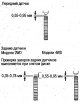
1. Check the signal discs for chips. Replace if necessary. 2. Check the gap between the wheel sensor and the signal disc. Standard clearance: Front sensors: 0.4-1.0 mm If the clearance is different from the specified...
1. Check the signal discs for chips. Replace if necessary. 2. Check the gap between the wheel sensor and the signal disc. Standard clearance: Front sensors: 0.4-1.0 mm If the clearance is different from the specified...
Wheel sensors — removal and installation
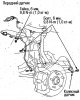
Caution: Do not twist the wheel sensor wiring during installation.
Caution: Do not twist the wheel sensor wiring during installation.
This section is available on: russian, bulgarian, belarusian, ukrainian, serbian, croatian, romanian, polish, slovak, hungarian
Link in different formats to this section
TEXTHTMLBB Code
- General information
- Controls and instruments
- User manual
- Power unit
- Engine maintenance
- Engine repair
- Cooling system
- Engine management
- Power and exhaust system
- Transmission
- Automatic gearbox
- Drive shafts and differential
- Chassis and running gear
- Steering
- Car suspension
- Brake system
- Body and interior
- Doors, locks and windows
- Interior (internal elements)
- Exterior (external elements)
- Air conditioner
- Electrical equipment
- Power devices
- Equipment and devices
- Headlights and lighting
- Electrical circuits