
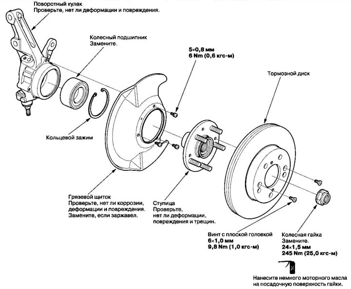
Replacing the steering knuckle/hub
1. Raise the front of the vehicle and support it securely.
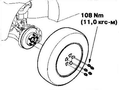
2. Remove the wheel cap, unscrew the wheel nuts and remove the front wheel.
3. Remove the mounting bolt (A) from the brake hose bracket.

4. Remove the mounting bolts (B) from the caliper bracket and remove the caliper assembly (C) from the steering knuckle. To avoid damaging the caliper or brake hose, tie the caliper assembly to the underbody with wire. Do not twist the brake hose with force.
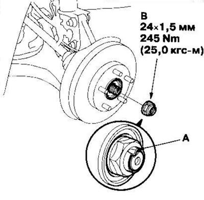
5. Bend back the locking tab (A) and unscrew the axle shaft nut (B).
6. Loosen the brake disc mounting screws (A).

7. Screw two 8x1.25mm bolts (B) into the disc and separate it from the hub. To avoid excessive disc tilt, tighten the bolts two turns at a time.
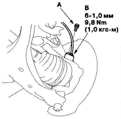
8. Loosen the flange bolt (A) and remove the wheel sensor (B) from the steering knuckle. Do not disconnect the connector from the wheel sensor.
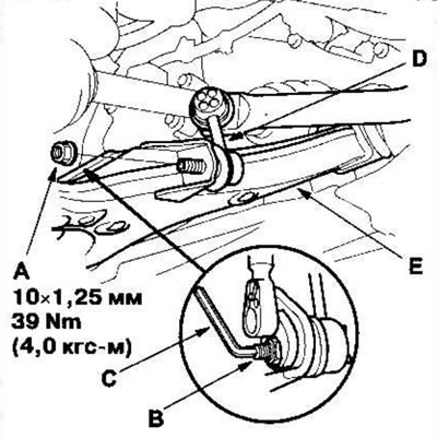
9. Loosen the flange nut (A) while holding the pivot pin (B) with the Allen key (C) and separate the stabilizer link (D) from the lower arm (E).
10. Remove the cotter pin (A) from the lower control arm ball joint and unscrew the castle nut (B).

Note: When installing, place the cotter pin on the ball joint pin from the inside of the vehicle to the outside. The closed part of the cotter pin must protrude to the specified length.
11. Separate the lower arm from the steering knuckle using a special tool.
12. Loosen the shock absorber tie bolts (A) while holding the nuts (B) and remove the bolts and nuts.

13. Tilt the steering knuckle outward and remove the drive shaft outer joint (C) from the steering knuckle (D) by tapping the end of the drive shaft (E) with a plastic hammer, then remove the steering knuckle.
Note: Do not pull the drive shaft outward, otherwise the drive shaft joint may break.
14. Remove the brake disc from the steering knuckle.
15. Installation of the steering knuckle/hub is performed in the reverse order of removal, taking into account the following:
- When installing the steering knuckles, do not damage the ball joint boots.
- Tighten all fasteners to the specified torque.
- First install all components and lightly tighten bolts and nuts, then raise the suspension to support the weight of the vehicle and fully tighten fasteners to the specified torque. Do not place a jack under the ball joint pin on the lower control arm.
- Tighten the castle nuts to the lower tolerance limit, then tighten just enough to align the slot with the cotter pin hole. Don't do this by loosening the nut.
- After tightening, install new cotter pins onto the castle nuts.
- When assembling, install new nuts on the axle shafts.
- Before tightening the axle nut, apply a small amount of engine oil to the seating surface of the nut. After tightening, use a drift to tap the axle nut shoulder into the groove on the drive shaft.
- Replace the self-locking nuts, tie bolts and shock absorber nuts with new ones.
- Before installing the brake disc, clean the contact surfaces on the front wheel hub and on the inside of the brake disc.
- Before installing the wheel, clean the contact surfaces on the brake disc and on the inside of the wheel.
- Check the front wheel alignment angles and adjust if necessary.
(The original text of the article is located on the website: «Hondabook.ru»)