
Note: Standard battery voltage is 12 V.
Female connector on harness side
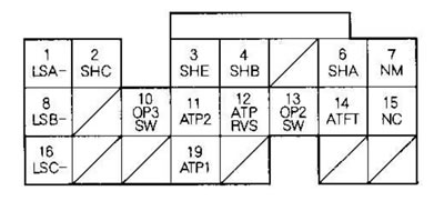
| contact No | Wire color | Contact name | Description | Signal |
| 1 | White with black stripe | LSA- (side - solenoid valve A for pressure regulation in automatic transmission) | Grounding for solenoid valve A for pressure regulation in automatic transmission | |
| 2 | Green | SHC (electrovalve C gear shift) | The gear shift solenoid valve C is activated | The engine is running in neutral or in position D, M (in 1st, 3rd, 5th gear): battery voltage The engine runs in the Park, R position or in the D, M position (in 2nd, 4th gear): about 0 V |
| 3 | Yellow | SHE (electrovalve E gear shift) | The gear shift solenoid valve E is activated | Engine running in Park, R position: battery voltage The engine is running in neutral or in position D, M (in 1st, 2nd, 3rd, 4th, 5th gears): about 0 V |
| 4 | Green with white stripe | SHB (electrovalve B gear shift) | The solenoid valve B for gear shifting is activated | The engine runs in Park, R, Neutral or D, M position (in 1st, 2nd gear): battery voltage The engine operates in position D, M (in 3rd, 4th, 5th gear): about 0V |
| 6 | Blue with black stripe | SHA (gear shift solenoid valve A) | The gear shift solenoid valve A is activated | The engine runs in position R or in position D, M (in 1st, 4th, 5th gear): battery voltage The engine runs in Park, Neutral or D, M position (in 2nd, 3rd gear): about 0 V |
| 7 | White with red stripe | NM (secondary shaft speed sensor) | Secondary shaft speed sensor signals are detected | Engine running: pulses |
| 8 | Black with red stripe | LSB-(side - solenoid valve B for pressure regulation in automatic transmission) | Grounding for the solenoid valve B for regulating the pressure in the automatic transmission | |
| 10 | Blue with white stripe | OP3SW (3rd gear oil pressure switch) | 3rd gear oil pressure switch detected | Ignition key in position ON (II): about 5 V Engine running in 3rd gear: about 0 V |
| 11 | Green with red stripe | ATR2 (2nd position of the gearbox range selector) | Detected 2nd gear range switch signal | In 2nd position: about 0 V In all other positions: battery voltage |
| 12 | Red with white stripe | ATPRVS (gearbox range selector position R) | Detected transmission range switch R position signal | In position R: about 0 V In all other positions: about 5 V or battery voltage |
| 13 | Blue with red stripe | OP2SW (2nd gear oil pressure switch) | 2nd gear oil pressure switch detected | Ignition key in position ON (II): about 5 V Engine running in 2nd gear: about 0 V |
| 14 | Red with yellow stripe | ATFT (aTF temperature sensor) | ATF temperature sensor signal is detected | Ignition key in position ON (II): about 0.1-4.2 V (depending on ATF temperature) |
| 15 | Blue | NC (intermediate shaft speed sensor) | Signals from the intermediate shaft speed sensor are detected | Ignition key in position ON (II) and front wheels turning: pulses |
| 16 | White with blue stripe | LSC-(side - solenoid valve C for pressure regulation in automatic transmission) | Grounding for the solenoid valve C for regulating pressure in the automatic transmission | Ignition key in position ON (II): depending on the mode |
| 19 | Brown | ATR1 (1st position of the gearbox range selector) | Detected signal of 1st position of gearbox range switch | In 1st position: about 0 V In all other positions: battery voltage |
* 1: models with automatic transmission
*2: models with manual transmission
*3: Models with TWC catalytic converter
*4: models KG, KS, KE, KR, KU, KZ, FO, KQ, KK, KM
*5: KG, KS, KE, KR, KU models (Hong Kong)
*6: models KG, KS, KE, KR, KU, KZ, FO, KQ
*7: models KG, KS, KE, KR, KU, KN, KN, KY, KZ, FO, KQ, KK, KM
*8: except for models KG, KS, KE, KR, KU, KN, KN, KH KZ, FO, KQ, KK, KM
*9: Except models with TWC catalytic converter
*10: models with cruise control