
Note: Standard battery voltage is 12 V.
Female connector on harness side
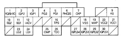
| contact No | Wire color | Contact name | Description | Signal |
| 1*3 | Black with white stripe | PO2SHTC (control of the heating element of the primary heated oxygen sensor) | Includes primary HO2S heating element | Ignition key in position ON (II): battery voltage Engine fully warmed up and running: depending on mode |
| 2 | Yellow with black stripe | IGP2 (power supply) | Power Supply for ECM/PCM Circuit | Ignition key in position ON (II): battery voltage Ignition key in position OFF about 0 V |
| 3 | Yellow with black stripe | IGP1 (power supply) | Power Supply for ECM/PCM Circuit | Ignition key in the ON position (H): battery voltage Ignition key in the OFF position about 0 V |
| 4 | Black | PG2 (power supply ground) | Ground for ECM/PCM circuit | Constantly less than 1.0 V |
| 5 | Black | PG1 (power supply ground) | Ground for ECM/PCM circuit | Constantly less than 1.0 V |
| 6*3 | Red | PHO2S (primary Heated Oxygen Sensor, Sensor 1) | Primary HO2S (Sensor 1) signal is detected | Throttle valve fully open, engine fully warmed up and running at idle speed: about 0.6 V Throttle valve quickly closing: below 0.4 V |
| 7 | Blue | Investigative Committee of Russia (crankshaft position sensor) | The signal from the CKP sensor is detected | Engine running: pulses |
| 9 | Red with blue stripe | KS (knock sensor) | Knock sensor signal detected | Ignition switch in position ON (II): about 0 V [MI] Engine produces detonation: pulses |
| 10 | Green with yellow stripe | SG2 (sensor ground) | "Mass" of the sensor | Constantly less than 1.0 V |
| 11 | Green with white stripe | SG1 (sensor ground) | "Mass" of the sensor | Constantly less than 1.0 V |
| 12 | Black with red stripe | IACV (idle speed air supply control valve.) | The IAC valve is turned on | Engine runs: depending on the mode |
| 15 | Red with black stripe | TPS (throttle position sensor) | TP sensor signal is detected | Throttle fully open: about 4.8 V Throttle fully closed: about 0.5 V |
| 18*2 | White with green stripe | VSS (vehicle speed sensor) | VSS sensor signal detected | Ignition switch in position ON (II) and front wheels turning: changes from approximately 0 to 5 V or battery voltage |
| 19 | Green with red stripe | MAR (manifold Absolute Pressure Sensor) | MAP sensor signal detected | Ignition key in position ON (11): about 3 V At idle speed: about 1 V (depending on engine speed) |
| 20 | Yellow with blue stripe | VCC2 (voltage on the sensor) | Voltage is applied to the sensor | Ignition key in position ON (II): about 5 V Ignition key in position OFF: about 0 V |
| 21 | Yellow with red stripe | VCC1 (voltage on the sensor) | Voltage is applied to the sensor | Ignition key in position ON (II): about 5 V Ignition key in position OFF: about 0 V |
| 23 | Brown with yellow stripe | LG2 (logic circuit ground) | Ground for ECM/PCM circuit | Constantly less than 1.0 V |
| 24 | Brown with yellow stripe | LG1 (logic circuit ground) | Ground for ECM/PCM circuit | Constantly less than 1.0 V |
| 25 | Blue with white stripe | Construction and installation work (camshaft position sensor) | The signal from the CMP sensor is detected | Engine running: pulses |
| 26 | Green | TDC (top dead center sensor) | TDC sensor detected | Engine running: pulses |
| 27 | Brown | IGPLS4 (ignition coil pulse no. 4) | Ignition coil #4 is turned on | Ignition key in position ON (II): about 0 V Engine running: pulses |
| 28 | White with blue stripe | IGPLS3 (ignition coil pulse #3) | Ignition coil #3 is turned on | |
| 29 | Blue with red stripe | IGPLS2 (ignition coil pulse #2) | Ignition coil #2 is turned on | |
| 30 | Yellow with green stripe | IGPLS1 (ignition coil pulse Na 1) | Ignition coil #1 is turned on |
*1: models with automatic transmission
*2: models with manual transmission
*3: Models with TWC catalytic converter
*4: models KG, KS, KE, KR, KU, KZ, FO, KQ, KK, KM
*5: KG, KS, KE, KR, KU models (Hong Kong)
*6: models KG, KS, KE, KR, KU, KZ, FO, KQ
*7: models KG, KS, KE, KR, KU, KN, KN, KX KZ, FO, KQ, KK, KM
*8: except for models KG, KS, KE, KR, KU, KN, KN, KH KZ, FO, KQ, KK, KM
*9: Except models with TWC catalytic converter
*10: models with cruise control
Information obtained from this source hondabook.ru