
Note: Standard battery voltage is 12 V.
Female connector on harness side
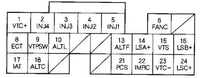
| contact No | Wire color | Contact name | Description | Signal |
| 1 | Blue with white stripe | VTC+ (side + of VTC oil solenoid valve) | VTC oil solenoid valve activation | Ignition key in position ON (II): 0 V |
| 2 | Yellow | INJ4 (fuel injector #4) | Fuel injector #4 on | At idle speed: depending on the mode. Ignition switch in position ON (II): battery voltage. |
| 3 | Blue | INJ3 (fuel injector #3) | Fuel injector #3 on | |
| 4 | Red | INJ2 (fuel injector #2) | Fuel injector #2 on | |
| 5 | Brown | INJ1 (fuel injector #1) | Fuel injector #1 on | |
| 6 | Green | FANC (radiator fan control) | Radiator Fan Relay On | Radiator fan running: about 0 V. Radiator Fan Not Working: Battery Voltage |
| 8 | Red with white stripe | EST (engine Coolant Temperature Sensor) | ECT sensor signal detected | Ignition key in position ON (II): about 0.1-4.8 V (depending on the engine coolant temperature) |
| 9*5 | Blue with black stripe | VTPSW (vTEC oil pressure switch) | VTEC Oil Pressure Switch Signal Detected | At idle speed: about 0 V |
| 10 | White with blue stripe | ALTL(generator signal) | Generator signal is detected | Ignition key in the ON (It) position: about 0 V. Engine running: battery voltage |
| 13 | White with red stripe | ALTF(fR generator signal) | FR generator signal is detected | Engine running: about 0-5 V (depending on the electrical load) |
| 14*1 | Red with black stripe | LSA+ (side + of the solenoid valve A for regulating pressure in the automatic transmission) | The solenoid valve A for regulating the pressure in the automatic transmission is switched on | Ignition key in position ON (II): depending on the mode |
| 15 | Green with yellow stripe | VTS (solenoid valve UTES) | The UTES solenoid valve is switched on | At idle speed: about 0 V |
| 16*1 | Brown with white stripe | LSB+ (side + of the solenoid valve B for regulating pressure in the automatic transmission) | The solenoid valve B for regulating the pressure in the automatic transmission is switched on | Ignition key in position ON (II): depending on the mode |
| 17 | Red with yellow stripe | IAT (intake air temperature sensor) | IAT sensor signal detected | Ignition key in position ON (II): about 0.1-4.8 V (depending on the intake air temperature) |
| 18*4 | White with green stripe | ALTC (generator control) | The control signal is transmitted to the generator | Engine running: about 0-5 V (depending on the electrical load) |
| 21 | Yellow with blue stripe | PCS (fuel vapor recovery carbon canister purge valve) | The EVAP canister purge valve is activated | Engine running, engine coolant temperature below 65°C: about 0 V. Engine running, engine coolant temperature above 65°C: depending on mode |
| 22 | Red with blue stripe | IMRC (intake manifold regulator control solenoid valve) | The IMRC solenoid valve is activated | At engine speeds below 4700 rpm (min1) (engine K24A1: 4300 min (min1): battery voltage At engine speeds over 4700 rpm (min1) (engine K24A1: 4300 min (min1): 0 V |
| 23 | Black with white stripe | VTC- (side - oil solenoid valve VTC) | The VTC oil solenoid valve is activated | Ignition key in position ON (II): 0 V |
| 24*1 | Blue with yellow stripe | LSC+ (side + of the solenoid valve C for pressure regulation in the automatic transmission) | The solenoid valve C for regulating the pressure in the automatic transmission is switched on | Ignition key in position ON (II): depending on the mode |
* 1: models with automatic transmission
*2: models with manual transmission
*3: Models with TWO neutralizer
*4: models KG, KS, KE, KR, KU. KZ, FO, KQ, KK, KM
*5: KG, KS, KE, KR, KU models (Hong Kong)
*6: models KG, KS, KE, KR, KU, KZ, FO, KQ
*7: models KG, KS, KE, KR, KU. KN, KN, KY KZ, FO, KQ, KK, KM
*8: Except for models KG, KS, KE, KR, KU, KN, KN, KH KZ, FO, KQ, KK, KM
*9: Except models with TWC catalytic converter
*10: models with cruise control
[Original published on this resource: hondabook]