
Contents: Removal ⇊ Installation ⇊
Caution! Wait until the engine has completely cooled down before starting work.
Removal
1. Disconnect the negative cable from the battery.
Warning! If the car stereo system is equipped with a security code, make sure you have the correct combination to activate the audio system before disconnecting the battery!
2. Release the pressure in the fuel system and disconnect the electrical wiring from the fuel injectors. Disconnect the fuel lines and remove the fuel lines (see Chapter Power and exhaust systems).
3. Drain the cooling system, including the engine block (see Chapter Settings and ongoing maintenance).
4. Remove the generator and distributor (see Chapter Engine electrical equipment).
5. Disconnect the ground bus from the wall of the power unit facing the timing belt.
6. Remove the steering pump (see Chapter Suspension and steering) and, without disconnecting the hoses, move it to the side.
7. Remove the upper intake manifold (see Section Removal and installation the intake manifold).
8. Remove the exhaust manifolds (see Section Removal and installation of exhaust manifolds).
9. Remove the timing belt and timing drive gears (see Section Removal, condition check and installation of the timing belt and timing drive gears).
10. Remove the rear timing belt covers (see Section Removal, condition check and installation of camshafts).
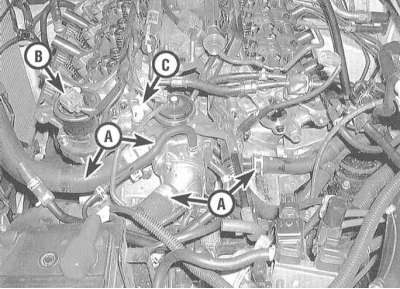
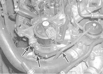
11. Separate the cooling tract channel assembly.
 |
 |
12. Remove the rocker arm assemblies with axles (see Section Removal, condition check and installation of rocker arm assembly).
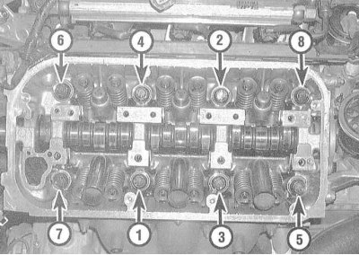
13. Using a socket wrench, loosen the cylinder head mounting bolts in several steps (1/4 turn per approach) until you can unscrew them by hand. Loosen the bolts in the reverse order to how they were tightened.
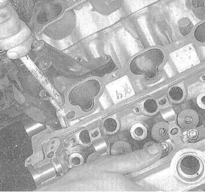
14. Remove the cylinder head from the engine. If the head does not separate from the block, you can use a lever, which should be inserted between the projections of the casting (under no circumstances should you pry the head under the mating surface).
15. Proceeding in the same order (see paragraphs 12 to 14), remove the second head. Check the flatness of both heads.
Installation
1. Thoroughly clean the mating surfaces of the cylinder heads and block. After scraping off the remaining gasket material and carbon deposits, wipe the surfaces with a rag soaked in acetone. The presence of old gasket material on the mating surfaces when installing the head may lead to a violation of the gasket's tightness and, as a result, to the development of leaks. When processing the block, plug the cylinder holes with a rag to prevent small debris and various foreign objects from getting into them (as a last resort, thoroughly vacuum the cylinders).
2. Check the mating surfaces of the heads and block for deep scratches, burrs, and other damage. Minor defects can be removed with fine-grained sandpaper. In more serious cases, the only alternative is to resurface or replace the components.
3. Using a tap of the appropriate size, run through the threaded holes for the head mounting bolts. After finishing the running, blow out the holes with compressed air. Clamping the bolts one by one in a vice by the head, go over their threads with a die - the presence of old sealant, dirt and corrosion products in the threads leads to a discrepancy between the actual tightening force of the fastener and the readings of the torque wrench indicator.
Note: When working with compressed air, do not forget to wear safety glasses!
4. Thoroughly clean the oil spray jets, replace their sealing rings. Lay new sealing gaskets, putting them on the oil spray jets and guide pins in the block.
5. Being careful not to displace the gasket, carefully place the head on the block.
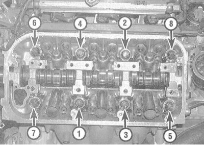
6. Lubricate the threads and the lower surfaces of the heads of the mounting bolts with clean engine oil and screw the fasteners into their original places (do not forget to put special washers under the heads). Tighten the bolts by hand. Acting in a strictly defined order, tighten the cylinder head mounting bolts in three stages with the required force (see Specifications).
Attention! All tightening stages must be duplicated twice, i.e., having tightened the bolts with the force of the first stage, repeat the procedure (tightening them with the same force), only then proceed to the second tightening stage, etc.
7. Proceeding in a similar manner, install the second cylinder head on the engine.
8. Installation of the remaining components is carried out in the reverse order of their dismantling.
9. Do not forget to fill the cooling system and replace the oil filter (see Chapter Settings and ongoing maintenance).
10. Start the engine and check that the ignition timing is set correctly (see Chapter Settings and ongoing maintenance). Let the engine run for about five minutes at low speed to remove air from the valve clearance adjuster assemblies. Make sure the unit is functioning properly.
Warning! During the first five minutes after initial start-up, the valve mechanism will operate with increased noise. If the noise level does not decrease, this may indicate a defect in one of the valve clearance adjusters.