
Examination
1. The suspension of the power unit on V6 models is carried out by means of four supports, the front and rear of which are equipped with hydraulic correctors, which can significantly reduce the level of vibration at idle engine speeds (see Section Powertrain Suspension Adjustment System - General Information and Functional Check).
2. To check, it is necessary to slightly raise the engine, unloading the supports.
3. Jack up the car and put it on stands. Place a jack under the engine sump (in order to distribute the load, lay a wooden block between the head of the jack and the pallet). Raise the jack by slightly raising the unit and unloading the supports.
Attention! Never carry out any work under the vehicle, which is held in a raised position with just a jack!
4. Check the support pads for cracks, signs of hardened rubber and delamination from the metal base.
5. Estimate the amount of play between the support plates and the power unit / vehicle frame (use a pry bar or a large screwdriver as a lever). If play is detected, lower the unit and tighten the support fasteners.
6. Pillows in order to avoid the destruction of rubber must be treated with a special protective compound.
Replacement
Disconnect the negative cable from the battery.
Note. If the stereo system installed in the car is equipped with a security code, before disconnecting the battery, make sure that you have the correct combination to activate the audio system! Apply the parking brake, jack up the front of the vehicle and place it on jack stands. Support the engine.
Right support (passenger side)
1. Support the transmission with a jack, completely unloading the right suspension bracket of the power unit.
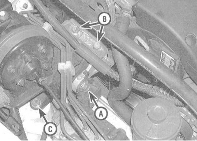
. Turn out a through bolt, give a bolt of fastening to an arm of the engine of an electric cable, then give two bolts of fastening of an arm of a support on the engine. Turn out three bolts of fastening of a support to the car chassis and remove a rubber pillow.
3. Installation is carried out in the reverse order.
Note. The final tightening of the support fasteners with the required force should be carried out only after lowering the power unit to its normal position. Proceed with the procedures listed in the Final Step of Tightening All Supports Fasteners.
Left support (from the driver's side)
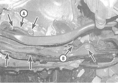
1. The left power unit suspension support is located under the transmission case and is fixed to the subframe.
2. Supporting the engine, give two nuts located under the subframe and two bolts securing the assembly to the transmission housing. Remove the pillow.
3. Installation is carried out in the reverse order.
Note. The final tightening of the support fasteners with the required force should be carried out only after lowering the power unit to its normal position. Proceed with the procedures listed in the Final Step of Tightening All Supports Fasteners.
Front support
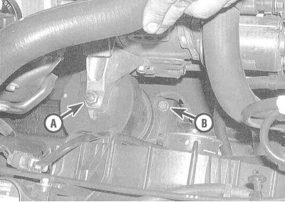
1. The power unit's front mount is located between the engine block and the radiator, and is equipped with a hydraulic adjustment device (see Section Powertrain Suspension Adjustment System - General Information and Functional Check).
2. Give the big nut screwed on the end of a fixing hairpin acting from an arm of the engine.
3. Turn out four bolts of fastening of a support to the chassis, then disconnect a vacuum hose from the bottom part of assembly.
4. Raise the engine just enough to release the stud from the top bracket. Remove assembly.
5. Installation is carried out in the reverse order.
Note. The final tightening of the support fasteners with the required force should be carried out only after lowering the power unit to its normal position. Proceed with the procedures listed in the Final Step of Tightening All Supports Fasteners.
Rear support
1. The rear support is located between the engine and the rear bulkhead of the engine compartment and, along with the front, is equipped with a hydraulic adjustment device (see Section Powertrain Suspension Adjustment System - General Information and Functional Check).
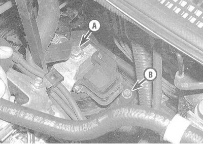
2. Give the large nut screwed onto the stud protruding from the engine bracket.
3. Turn out four bolts of fastening of a support to the chassis and disconnect a vacuum hose from the bottom part of assembly.
4. Raise the engine just enough so that the stud can be easily released from the top bracket. Remove assembly.
5. Installation is carried out in the reverse order.
Note. The final tightening of the support fasteners with the required force should be carried out only after lowering the power unit to its normal position. Proceed with the procedures listed in the Final Step of Tightening All Supports Fasteners.
The final stage of tightening the fasteners of all supports
1. In order to maximize the service life of rubber-metal bearings and reduce the level of noise and vibration, the final tightening of the bearing fasteners with the required force should be carried out after lowering the power unit to its normal position (the vehicle must be parked on a level surface).
Note. For lubricating the threaded part of fasteners (bolts and nuts) use non-hardening sealant.
2. Make sure that the rubber bushings are not twisted or displaced from their seats. If more than one support was replaced, as well as when installing the power unit, the support fasteners must be tightened in the following order:
- a) Front support;
- b) Rear support;
- c) Right support;
- d) Left support.