
Withdrawal
1. Remove cylinder head covers (see Section Removal and installation of covers of heads of cylinders), timing belt and gears (see Section Removing, checking the condition and installing the gas distribution belt and timing gears).
2. Remove the ignition distributor (see chapter Engine electrical equipment).
3. Remove rocker assemblies (see Section Removal, condition check and installation of rocker arm assembly).
4. Remove the EGR valve (see chapter Engine management) in order to provide access to the rear camshaft mounting plate.
Note. Before removing the camshafts, measure their end play.
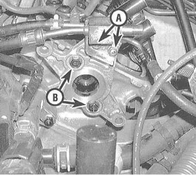
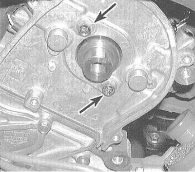
5. Remove the rear camshaft holder plate.
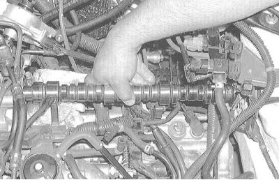
6. Gently remove the camshaft from the cylinder head, being careful not to damage its cams and journals.
Examination

1. Remembering the order of installation of individual parts, dismantle the rocker arm assembly, then bolt the axles freed from components to their regular places in the cylinder head. Tighten fasteners to the required torque.
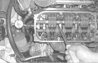
2. Fasten the dial gauge so that its plunger rests against the end of the camshaft. Pull the shaft back until it stops (wrap the end of the lever with adhesive tape to avoid damage to the working surfaces of the shaft), zero the meter, then slide the shaft all the way in the opposite direction. Read the meter reading, record the result and compare it with the regulatory requirements for camshaft end play (see Specifications). If the reading is out of range, the shaft must be replaced.
3. After checking the axial play, remove the rocker axles, then remove the shaft from the cylinder head. Measure the diameters of the necks and the height of the cams. Check measurements against requirements Specifications (for V6 engines). Visually assess the wear on the shafts - look for things like scratches, scuffs, cavities and signs of overheating.
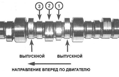
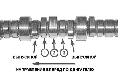
Note. Pay attention to the difference in the location of the cams on the front and rear camshafts.
 |  |
Installation
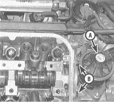
1. Remove the rear timing belt covers from both cylinder heads to provide access to the camshaft seals.
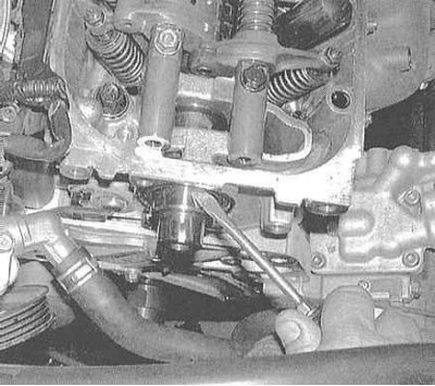
2. Oil seals must be replaced each time the head is disassembled/shafts are removed. Removing old oil seals is done by prying them with a special tool, or with a flat-bladed screwdriver.
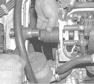
3. Lubricate the lips of the new oil seal with clean engine oil, then seat it perpendicularly into its seat to the same depth as the old oil seal was seated. As a mandrel for planting the gland, you can use an end head of the appropriate size, or a piece of pipe of a suitable diameter.
4. Thoroughly wipe the camshaft, the beds of its bearings in the cylinder head and covers, as well as the rocker arms of the valve drive with a rag soaked in acetone. Try to completely remove the slightest traces of sludge and dirt. Use only a clean, lint-free cloth to wipe components. Lubricate the necks and cams of the shaft with special assembly grease and carefully install the shaft in its regular place in its head.
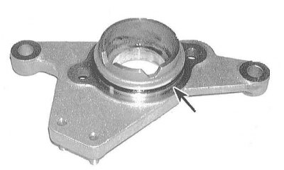
5. Lubricate and install a new O-ring on the shaft holder plate. Bolt the plate into place on the cylinder head.
6. Acting in a similar manner (see paragraphs 4 and 5), install a second camshaft in your cylinder head.
7. Reinstall all remaining components in reverse order of removal. Check valve clearance setting, adjust if necessary (see chapter Settings and ongoing maintenance).
8. Start the engine and check for oil leaks from the camshaft seals. Run the engine for about five minutes at low speed to purge air from the valve clearance adjuster assemblies. Check that the unit is functioning properly.
Note. In the first five minutes after the initial start, the valve train will operate with increased noise. If the noise level does not then decrease, this may indicate a defect in one of the valve clearance correctors.