Contents: VTC system ⇊ VTEC system ⇊ System diagram ⇊ Camshaft Position Angle (CMP) Sensor ⇊ Regulation of air supply at idle…⇊ Fuel supply system ⇊ Fuel cut-off regulator ⇊ Fuel pump regulator ⇊ PGM-FI Main Relay 1 & 2 ⇊ Power Steering Pump (PSP) Oil…⇊ Control valve for air supply at idle…⇊ Brake pedal position switch ⇊ Air supply system ⇊ Throttle body ⇊ Air supply bypass thermal valve ⇊ Catalytic converter system ⇊ Positive Crankcase Ventilation (PCV)…⇊ Fuel Evaporative Emissions (EVAP)…⇊ Scheme of the air supply control…⇊ Air supply system diagram ⇊ Intake Manifold Runner Regulator…⇊ Fuel Evaporative Protection (EVAP)…⇊
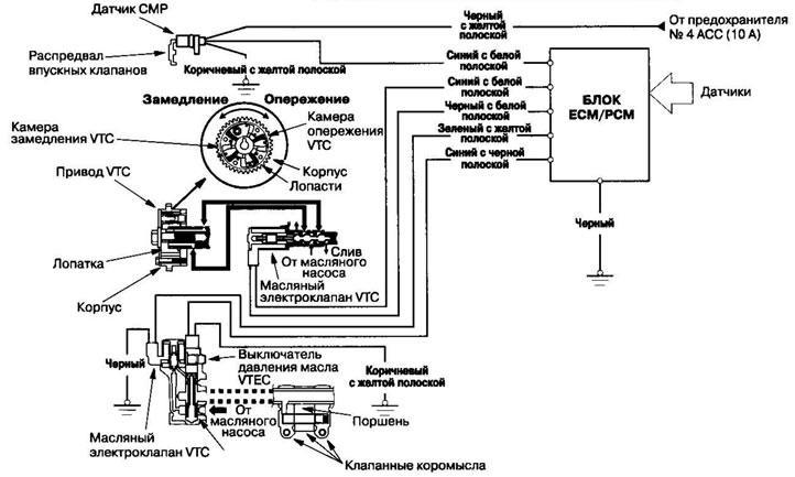
- In addition to the standard capabilities of conventional VTEC, the i-VTEC system has a VTC mechanism installed on the intake camshaft (variable valve timing), This mechanism increases fuel economy and reduces exhaust toxicity in all ranges of engine speed, vehicle speed and engine load.
- The VTEC mechanism varies the valve lift and timing by using cams with different profiles.
- The VTC mechanism changes the valve timing on the intake camshaft using oil pressure. The valve timing of the intake valves is adjusted continuously.
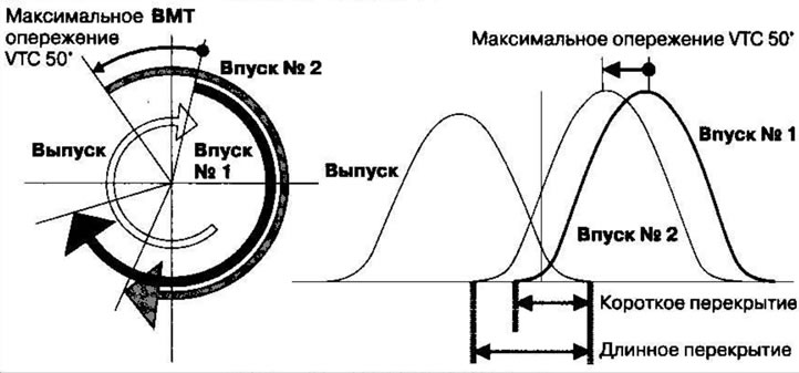
VTC system
- The VTC system continuously changes the valve timing of the intake valves based on engine operating conditions.
- The intake valve timing is adjusted so that the engine can develop maximum power.
- The camshaft angle is advanced to achieve exhaust gas recirculation and reduce pumping losses. The intake valve closes quickly, which helps to reduce the supply of fuel-air mixture to the intake port and increase filling.
- The cam angle advance at idle speed is reduced, combustion is stabilized and engine speed is reduced.
- If a fault occurs, the VTC system is disabled and the valve timing is switched to the fully retarded position.
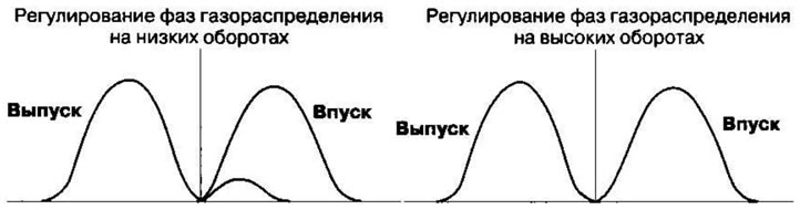
VTEC system
- The VTEC system changes the cam profile depending on engine speed. It increases torque at low engine speeds and power at high engine speeds.
- At low engine speeds, a cam with a low lift height is used, at high engine speeds, a cam with a high lift height is used.
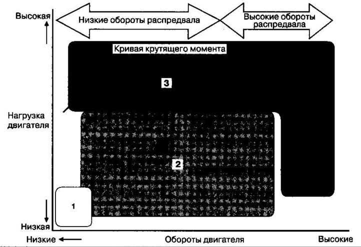
| Driving mode | VTC regulation | Description |
| 1. Light load | Basic position | The angle of the camshaft is delayed, the supply of exhaust gases to the intake channel is reduced and stable fuel consumption is achieved when burning a lean mixture. |
| 2. Medium/high load | Timing advance regulation | The camshaft angle is advanced to recirculate exhaust gases and reduce pumping losses. The intake valve closes quickly, which helps to reduce the supply of fuel-air mixture to the intake port and increase filling. |
| 3. High revs | Advance-basic position | The cam phase angle is adjusted to achieve optimal valve timing and maximum engine power. |
System diagram
Camshaft Position Angle (CMP) Sensor
The CMP sensor detects the angular position of the camshaft for the VTC system.
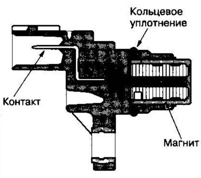
Regulation of air supply at idle speed.
When the engine is cold, the A/C compressor is on, the transmission is in gear, the brake pedal is depressed, the power steering load is high, or the alternator is charging, the ECM/PCM regulates the current to the IAC valve to maintain the proper idle speed. See the system diagram for the functional layout of the system.
Fuel supply system
Fuel cut-off regulator
When decelerating with the throttle closed, the current from the fuel injectors is cut off to reduce fuel consumption at speeds above 850 rpm (on models KH KN, RN, KR, IN: 900 rpm). Fuel cutoff also occurs at engine speeds above 6900 rpm (k24A1 engine: 6700 rpm) regardless of the throttle position to prevent the engine from running at maximum speed. When the vehicle is stopped, the ECM/PCM cuts off the fuel supply at engine speeds above 6500 rpm (Automatic transmission: 5000 rpm).
Fuel pump regulator
When the ignition is turned on, the ECM/PCM grounds the PGM-FI main relay, which energizes the fuel pump for 2 seconds to pressurize the fuel system. When the engine is running, the ECM/PCM grounds the PGM-FI main relay and supplies current to the fuel pump. When the engine is not running but the ignition is on, the ECM/PCM interrupts the ground to the PGM-FI main relay, which cuts current from the fuel pump.
PGM-FI Main Relay 1 & 2
The PGM-FI relay consists of two separate relays. PGM-FI main relay 1 is energized when the ignition switch is turned to the ON (II) position and supplies battery voltage to the ECM/PCM, power to the fuel injectors, and PGM-FI main relay 2. PGM-FI main relay 2 is energized for two seconds when the ignition switch is turned to the ON (II) position and while the engine is running and supplies power to the fuel pump.
Power Steering Pump (PSP) Oil Pressure Switch
The PSP switch signals the ECM/PCM when the load on the power steering increases.
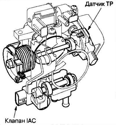
Control valve for air supply at idle speed (IAC)
To maintain the proper idle speed, the IAC valve varies the air flow bypassing the throttle body in response to an electrical signal from the ECM/PCM.
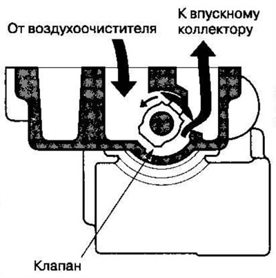
Brake pedal position switch
The brake pedal position switch sends a signal to the ECM/PCM when the brake pedal is depressed.
Air supply system
See the system diagram for the functional layout of the system.
Throttle body
The throttle body is a single chamber side-pull design. The bottom of the IAC valve is heated by engine coolant from the cylinder head.
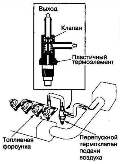
Air supply bypass thermal valve
When the engine is running, the bypass thermostat valve supplies air to the fuel injectors.
Catalytic converter system
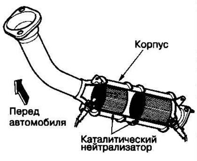
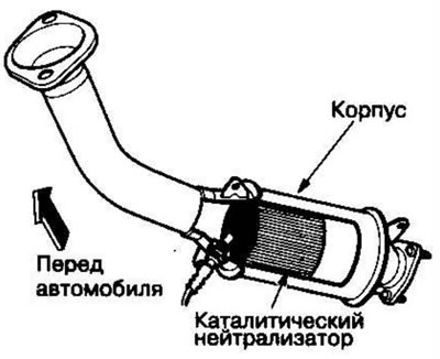
Three-way catalytic converter (TWC)
The TWC catalytic converter is used to convert hydrocarbons (HC), carbon monoxide (CO) and nitrogen oxides (NOx) contained in exhaust gases into carbon dioxide (CO₂), nitrogen (N₂) and water vapor.
Models KG, KS, KE, KR, KU, KZ, GO, KQ
Models KN, KM, KY, MA, PH, IN, KK
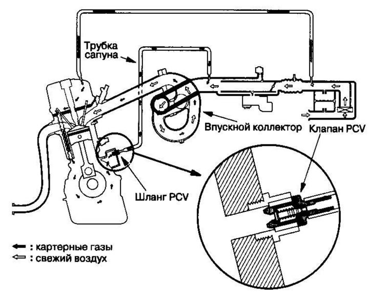
Positive Crankcase Ventilation (PCV) System
The PCV valve prevents crankcase gases from entering the atmosphere by diverting them into the intake manifold.
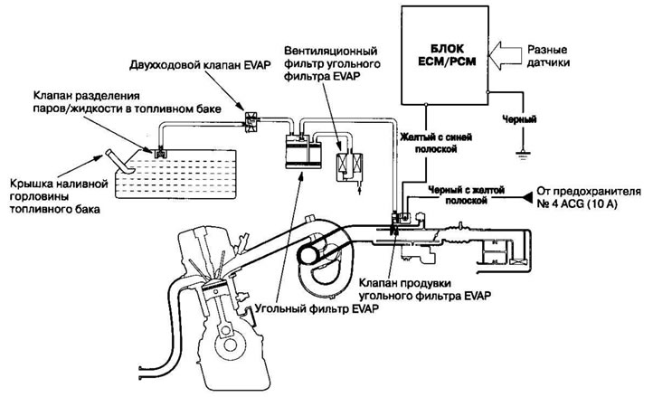
Fuel Evaporative Emissions (EVAP) System*
See the system diagram for the functional layout of the system.
Carbon filter for Fuel Vapor Capture (EVAP)
The EVAP carbon canister is used to temporarily store fuel vapors coming from the fuel tank until they can be blown out of the canister into the engine and burned.
EVAP Carbon Canister Purge Valve
When the engine coolant temperature is below 65°C, the ECM/PCM deactivates the EVAP canister purge valve, which cuts off the vacuum from the EVAR canister
Scheme of the air supply control system at idle speed.
The engine idle speed is controlled by the IAC valve:
- After the engine starts, the IAC valve opens for a while. Air flow increases, increasing idle speed.
- When the engine coolant temperature is low, the required fast idle speed is achieved by opening the IAC valve. In this way, the air flow supplied bypassing the throttle valve is controlled proportionally to the engine coolant temperature.
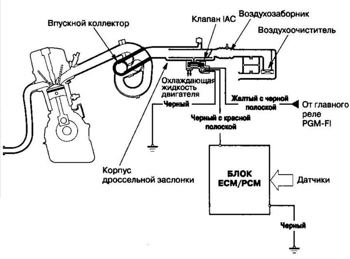
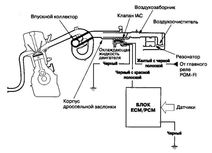
Air supply system diagram
The system provides air supply for all engine operating modes. The resonator built into the air intake pipe provides additional noise insulation when air is sucked into the system.
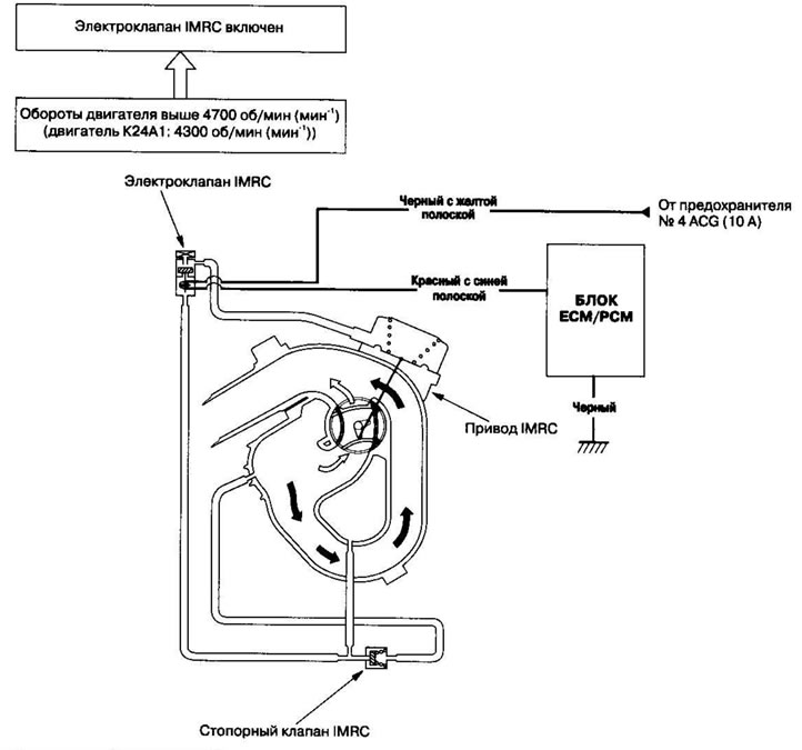
Intake Manifold Runner Regulator (IMRC) System
Satisfactory power characteristics are achieved by opening and closing the Intake Manifold Runner Control (IMRC) valve. High torque at low engine speeds is achieved with the valve closed, while high power is achieved with the valve open.
Fuel Evaporative Protection (EVAP) Circuit
The EVAP system serves to reduce the emission of fuel vapors into the atmosphere. Fuel vapors exiting the fuel tank are temporarily stored in the EVAP canister until they can be blown from the canister into the engine and burned.
- Purging the EVAP canister is accomplished by drawing fresh air through it and into a passage in the intake manifold.
- The purge vacuum is controlled by the EVAP canister purge valve, which opens when the engine coolant temperature reaches above 65°C.
- When the fuel vapor pressure in the fuel tank is higher than the set value on the EVAP valve, the valve opens and regulates the flow of fuel vapor to the EVAP canister.