
Contents: ABS indicator ⇊ Trouble Codes (DTC) ⇊ Self-diagnosis ⇊ Back push ⇊ Pump electric motor ⇊ How to Check DTCs When an ABS…⇊ How to read DTC codes from the ABS…⇊ Clearing DTCs from the ABS system…⇊ Description of the system ⇊ Characteristics ⇊
ABS indicator
- If the system is normal, the ABS indicator goes out 2 seconds after the ignition key is turned to the ON (II) position without starting the engine, then comes on again and goes out 2 seconds after the engine is started. This happens because the ABS control unit is powered by the IG1 power supply.
- The ABS indicator comes on when the ABS control unit detects a fault in the system. However, even if the system is working properly, the ABS indicator will come on under the following conditions:
- Only the drive wheels rotate.
- One drive wheel is stuck.
- The car is slipping.
- The ABS system continues to work for a very long time.
- Interference with electrical signals.
- To determine the actual cause of the malfunction, it is necessary to know exactly the conditions under which the indicator lights up.
- When a malfunction is detected and the ABS indicator comes on, there are cases where the indicator remains on unless the ignition key is turned to the OFF position, and cases where the indicator goes out automatically when the system returns to normal.
- DTC Codes 61,62: The ABS indicator turns off automatically when the system returns to normal.
- DTCs 11, 13, 15, 17, 31, 32, 33, 34, 35, 36, 37, 38, 54 or 81: The ABS indicator remains on until the ignition switch is turned to the OFF position regardless of whether the system returns to normal or not.
- DTCs 12, 14, 16, 18, 21, 22, 23, 24, 51, 52, or 53: The ABS indicator goes out after the vehicle is driven again and the system returns to normal after the ignition switch is turned from OFF to ON (II).
Trouble Codes (DTC)
- Three DTCs can be stored in the memory. However, when the same DTC is detected two or more times, the old code is overwritten by the new one. Thus, if the same malfunction is detected multiple times, it is recorded as one DTC code.
- DTCs are displayed in the order they occur, starting with the most recent.
- DTC codes are written to the EEPROM (non-volatile memory). Therefore, DTCs stored in memory cannot be cleared by disconnecting the battery, turning the ignition switch from the OFF position, or returning the system to normal. To clear DTCs, perform the required procedures.
Self-diagnosis
- Self-diagnosis can be divided into the following two categories:
- Primary diagnostics: Performed immediately after starting the engine until the ABS indicator goes out.
- Routine diagnostics: Performed immediately after the initial diagnostics before turning the ignition key to the OFF position.
- If a malfunction is detected during self-diagnosis, the system performs the following actions.
- The ABS indicator lights up
- Writes DTC code to memory
- Stops the ABS system from working
Back push
The pump's electric motor is activated when the ABS system is activated and fluid from the reservoir is supplied to the master cylinder, causing a reverse push on the brake pedal.
Pump electric motor
- The pump electric motor is activated when the ABS system is activated.
- The ABS control unit checks the operation of the pump motor when the vehicle is first driven after turning the ignition key to the ON (II) position, at this point you may hear the motor running, but this is normal.
How to Check DTCs When an ABS Problem Occurs
The troubleshooting flow chart assumes that the cause of the fault is still present and the ABS indicator is still on. Following the flow chart logic when the ABS indicator is not on may result in erroneous diagnostic results.
The diagrams show the connectors as follows: the female connectors are outlined by a single-circuit line on the contact side, and the male connectors are outlined by a double-circuit line on the contact side.
1. Determine the conditions under which the fault occurred and try to reproduce them to troubleshoot the fault. Find out when the ABS indicator came on, such as while the ABS system was operating, after the ABS system was operating, when the vehicle was moving at a certain speed, etc.
2. When the ABS indicator does not come on during a test drive but troubleshooting is performed by DTC, check whether the connectors are tightly connected, whether the contacts are loose, etc. before starting the troubleshooting.
3. After troubleshooting is complete, clear the DTC from the memory and test drive the vehicle. Make sure the ABS indicator does not come on.
How to read DTC codes from the ABS system memory
Using the HONDA PGM tester
1. Turn the ignition switch to the OFF position and connect the Honda PGM Tester (A) to the 16-pin data link connector (DLC) (B) located on the right side of the fuse/relay box (B) under the instrument panel.
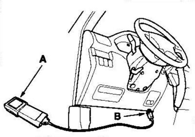
2. Turn the ignition switch to the ON (II) position and follow the tester's instructions to help you display the DTC codes on the screen. Once you have identified the DTCs, refer to the DTC table.
Note: For specific operations, see. in the owner's manual that comes with the Honda PGM tester.
Using the diagnostic connector jumper (on European models)
1. Turn the ignition switch to the OFF position and connect the SCS jumper (A) to the 2-pin diagnostic connector (B) located on the right side of the fuse/relay box under the instrument panel.
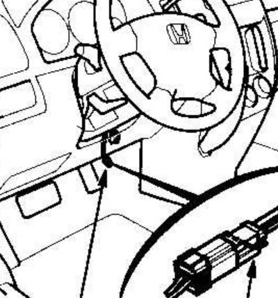
2. Turn the ignition key to the ON (II) position without pressing the brake pedal.
Note: If you press the brake pedal while turning the ignition switch to the ON (II) position, the system will enter the DTC memory erasure mode.
3. Frequency (quantity) flashes (blinks) of the ABS indicator indicate the DTC code. It consists of a sequence of long and short flashes. One long flash is equal to 10 short flashes. The DTC code is determined by adding together the long and short flashes. Once you have identified the DTC, refer to the trouble code table (example of reading DTC codes in the picture).
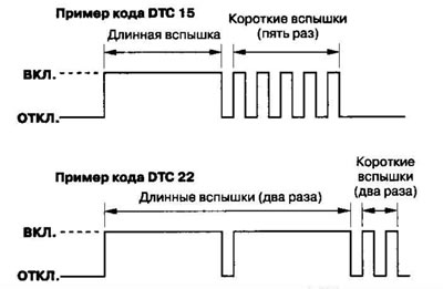
Note: If the DTC is not stored in memory, the ABS indicator will go out for 3.6 seconds and then come on again.
The system will not display a DTC unless the following conditions are met:
- The ignition key is turned to the ON (II) position.
- The diagnostic connector is shorted to ground before turning the ignition key to the ON (II) position.
4. Turn the ignition key to the OFF position.
5. Remove the jumper from the diagnostic connector.
Using the DLC contact block (except for European models)
1. Turn the ignition switch to the OFF position and connect the DLC connector (A) to the 16-pin data link connector (DLC) (B) located on the right side of the fuse/relay box under the instrument panel.
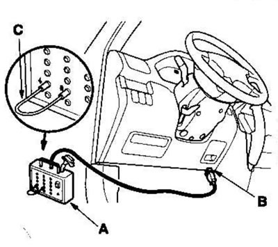
2. Insert the jumper wire tips (C) into the No. 4 and No. 9 sockets of the DLC terminal block and press the switch.
3. Turn the ignition key to the ON (II) position without pressing the brake pedal.
Note: If you press the brake pedal while turning the ignition switch to the ON (II) position, the system will enter the DTC memory erasure mode.
4. Frequency (quantity) flashes (blinks) of the ABS indicator indicate the DTC code. It consists of a sequence of long and short flashes. One long flash is equal to 10 short flashes. The DTC code is determined by adding together the long and short flashes. Once you have identified the DTC, refer to the DTC table.
Note: If the DTC is not stored in memory, the ABS indicator will go out for 3.6 seconds and then come on again.
The system will not display a DTC unless the following conditions are met:
- The brake pedal is not pressed.
- The ignition key is turned to the ON (II) position.
- The diagnostic connector is shorted to ground before turning the ignition key to the ON (II) position.
5. Turn the ignition key to the OFF position.
6. Disconnect the DLC connector from the DLC connector.
Clearing DTCs from the ABS system memory
Using the HONDA PGM tester
1. Turn the ignition switch to the OFF position and connect the Honda PGM Tester (A) to the 16-pin data link connector (DLC) (B) located under the driver's side of the instrument panel.
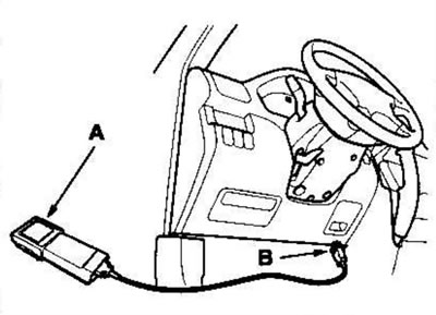
2. Turn the ignition switch to the ON (II) position and clear the DTCs following the instructions on the Honda PGM Tester screen.
Note: For specific operations, see. in the owner's manual that comes with the Honda PGM tester.
Using the diagnostic connector jumper (except for European models)
1. Turn the ignition switch to the OFF position and connect the SCS jumper (A) to the 2-pin diagnostic connector (B) located on the right side of the fuse/relay box under the instrument panel.
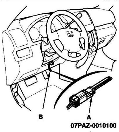
2. Press the brake pedal.
3. Turn the ignition key to the ON (II) position while keeping the brake pedal depressed.
4. After the ABS indicator goes out, release the brake pedal.
5. After the indicator lights up, press the brake pedal again.
6. After the indicator goes out, release the brake pedal.
DTCs cannot be cleared unless the following conditions are met:
- The vehicle speed is 10 km/h or less.
- The diagnostic connector is shorted to ground before turning the ignition key to the ON (II) position.
- The brake pedal is depressed before turning the ignition key to the ON (II) position.
7. After a few seconds, the ABS indicator will flash twice and the DTC will be cleared. If the indicator does not flash twice, repeat steps. 1-6. If the ABS indicator continues to illuminate after flashing twice, check for DTC because the malfunction was detected during primary diagnostics before entering DTC Clear mode.
8. Turn the ignition key to the OFF position.
9. Remove the jumper from the diagnostic connector.
Using the DLC contact block (except for European models)
1. Turn the ignition switch to the OFF position and connect the DLC connector (A) to the 16-pin data link connector (DLC) (B) located on the right side of the fuse/relay box under the instrument panel.
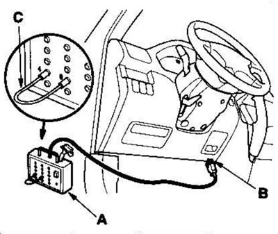
2. Insert the jumper wire tips (C) into the No. 4 and No. 9 sockets of the DLC terminal block and press the switch.
3. Press the brake pedal.
4. Turn the ignition key to the ON (II) position while keeping the brake pedal depressed.
5. After the ABS indicator goes out, release the brake pedal.
6. After the indicator lights up, press the brake pedal again.
7. After the indicator goes out, release the brake pedal.
DTCs cannot be cleared unless the following conditions are met:
- The vehicle speed is 10 km/h or less.
- The diagnostic connector is shorted to ground before turning the ignition key to the ON (II) position.
- The brake pedal is depressed before turning the ignition key to the ON (II) position.
8. After a few seconds, the ABS indicator will flash twice and the DTC will be cleared. If the indicator does not flash twice, repeat steps. 1-7. If the ABS indicator continues to illuminate after flashing twice, check for DTC because the malfunction was detected during primary diagnostics before entering DTC Clear mode.
9. Turn the ignition key to the OFF position.
10. Disconnect the DLC connector from the DLC connector.
Trouble Code (DTC) Table
| DTC code | Parameter |
| 11 | Right Front Wheel Sensor (open/short circuit to ground/short circuit with power supply) |
| 12 | Right Front Wheel Sensor (electrical interference/intermittent failure) |
| 13 | Left Front Wheel Sensor (open/short circuit to ground/short circuit with power supply) |
| 14 | Left Front Wheel Sensor (electrical interference/intermittent failure) |
| 15 | Right rear wheel sensor (open/short circuit to ground/short circuit with power supply) |
| 16 | Right rear wheel sensor (electrical interference/intermittent failure) |
| 17 | Left rear wheel sensor (open/short circuit to ground/short circuit with power supply) |
| 18 | Left rear wheel sensor (electrical interference/intermittent failure) |
| 21 | Right Front Wheel Pulse Generator |
| 22 | Left Front Wheel Pulse Generator |
| 23 | Right rear wheel pulse generator |
| 24 | Left rear wheel pulse generator |
| 31 | Solenoid |
| 32 | Solenoid |
| 33 | Solenoid |
| 34 | Solenoid |
| 35 | Solenoid |
| 36 | Solenoid |
| 37 | Solenoid |
| 38 | Solenoid |
| 51 | Electric motor blocking |
| 52 | The electric motor is stuck in the disconnected state (OFF) |
| 53 | The electric motor is stuck in the ON position |
| 54 | ABS system fail-safe relay |
| 61 | High voltage IG1 |
| 61 | Low voltage IG1 |
| 81 | CPU and ROM/RAM diagnostics |
Table of signs of malfunction
| Sign of malfunction | Diagnostic procedure |
| ABS indicator does not light | Troubleshooting the ABS Indicator Circuit |
| The ABS indicator does not go out and the DTC code is not stored in the memory | Troubleshooting the ABS Indicator Circuit |
| The brake system indicator does not light up | Troubleshooting the Brake System Indicator Circuit |
| The brake system indicator does not go out and the DTC code is not stored in the memory | Troubleshooting the Brake System Indicator Circuit |
Description of the system
ABS unit input and output signals on 47-pin connector
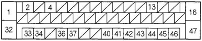
Female connector on the harness side.
| contact No | Wire color | Contact symbol (contact designation) | Description | Measurement (Disconnect the connector from the ABS control unit) | |||
| Contacts | Measurement conditions | Voltage | |||||
| 1 | White with red stripe | +B-R | Power supply for pump motor relay | 1-GND | Constantly | Battery voltage | |
| 2 | Grey | DIAG-II | Communication with Honda PGM tester is in progress | - | - | - | |
| 4 | Yellow | IG1 | Power supply to turn the system on | 4-GND | Ignition key in position ON (II) | Battery voltage | |
| 13 | Brown with yellow stripe | EBD | The brake system indicator is activated | 13-GND | Engine running, parking brake on | Tightened | Below 0.3 V |
| Released | Battery voltage | ||||||
| 16 | Black | GND-V | Ground for system/solenoid valve | - | - | - | |
| 32 | White with blue stripe | +В -V | Power supply for system/solenoid valve | 32-GND | Constantly | Battery voltage | |
| 33 | Blue | FR-GND | Signal from right front wheel sensor detected | - | - | - | |
| 34 | Green with black stripe | FR+B | |||||
| 36 | Yellow with red stripe | RL+B | Signal from left rear wheel sensor detected | - | - | - | |
| 37 | Gray with red stripe | RL-GND | |||||
| 40 | Brown | SCS | To display or clear a DTC code | - | - | - | |
| 41 | White with black stripe | stop | Signal from brake pedal position switch is detected | 41-GND | Brake pedal | Pressed | Battery voltage |
| Released | Below 0.3 V | ||||||
| 42 | Blue with yellow stripe | RR-GND | Signal from right rear wheel sensor detected | - | - | - | |
| 43 | Green with yellow stripe | RR+B | |||||
| 44 | Blue with red stripe | ABS | The ABS indicator is activated | 44-GND | Ignition key in position ON (II) | About 6 V | |
| 45 | Blue with orange stripe | FL+B | Signal from left front wheel sensor detected | - | - | - | |
| 46 | Brown with white stripe | FL-GND | |||||
| 47 | Black | GND-P | "Mass" for the pump electric motor | - | - | - | |
Characteristics
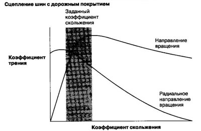
If you press the brake pedal while driving, the wheels may lock before the vehicle comes to a stop. If the front wheels lock, the vehicle's maneuverability is reduced; if the rear wheels lock, the vehicle's stability is reduced. In both cases, a dangerous situation is created. The ABS system precisely regulates the degree of wheel slippage and helps maintain the vehicle's maneuverability and stability.
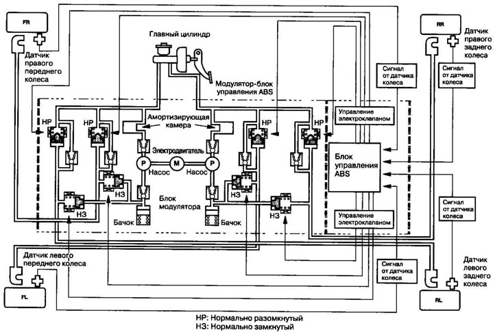
The ABS system calculates the wheel slip ratio based on the wheel speed and then distributes the brake fluid pressure to achieve the specified slip ratio.
| Components | Main purpose | |
| Wheel sensor | The wheel sensor transmits a speed signal to the ABS control unit in accordance with the speed of the magnetic sensor. | |
| Modulator-control unit | ABS control unit | The ABS control unit processes the signal from the wheel sensor and outputs a control signal to the modulator unit. |
| Modulator block | The modulator unit receives a control signal and regulates the fluid pressure in the brakes of all wheels. | |
[Full version on the source website: www.hondabook.ru]