


Car steering Honda HR-V 1

Location of steering components
Perform disassembly taking into account the following: When removing an undamaged airbag assembly from a vehicle being scrapped, or when defects or damage are discovered during transportation, storage or maintenance,...
Perform disassembly taking into account the following: When removing an undamaged airbag assembly from a vehicle being scrapped, or when defects or damage are discovered during transportation, storage or maintenance,...

Checking and adjusting the steering
Set the front wheels to the straight-ahead position and measure the distance the steering wheel can be turned without the front wheels moving. Steering wheel play: 0-10 mm. If the play is greater than the specified...
Set the front wheels to the straight-ahead position and measure the distance the steering wheel can be turned without the front wheels moving. Steering wheel play: 0-10 mm. If the play is greater than the specified...

Checking the power steering on a stationary vehicle
1. Check the power steering fluid level and the pump drive belt tension ( see further ). 2. Start the engine, let it run at idle speed and turn the steering wheel from lock to lock several times to warm up the fluid. 3....
1. Check the power steering fluid level and the pump drive belt tension ( see further ). 2. Start the engine, let it run at idle speed and turn the steering wheel from lock to lock several times to warm up the fluid. 3....

Steering drive and steering mechanism — design description
Note: Left hand drive model shown; the arrangement on the right-hand drive model is symmetrical. 1. TIE ROD END BALL JOINT. Check for binding or damage. 2. STEERING COLUMN. Check for looseness of the steering column...
Note: Left hand drive model shown; the arrangement on the right-hand drive model is symmetrical. 1. TIE ROD END BALL JOINT. Check for binding or damage. 2. STEERING COLUMN. Check for looseness of the steering column...

Pump Drive Belt — Checking and Adjusting
If a new belt is used, first adjust the sag or tension to the new belt value, then run the engine for five minutes and change the sag or tension adjustment to the used belt value. Examination Please perform the check...
If a new belt is used, first adjust the sag or tension to the new belt value, then run the engine for five minutes and change the sag or tension adjustment to the used belt value. Examination Please perform the check...

Adjusting the steering rack guide
1. Remove the rear support beam. 2. On left-hand drive vehicles, remove the floor heat shield. 3. On right-hand drive vehicles, remove the shift cable clamp (CVT models only). Remove the rear mount bracket from the...
1. Remove the rear support beam. 2. On left-hand drive vehicles, remove the floor heat shield. 3. On right-hand drive vehicles, remove the shift cable clamp (CVT models only). Remove the rear mount bracket from the...

Power Steering Fluid Replacement
Check the tank periodically and add fluid if necessary. Caution: Use only Genuine Honda Power Steering Fluid (V, II, or S). Use of other fluids, such as ATF or other brands of power steering fluid, will damage the...
Check the tank periodically and add fluid if necessary. Caution: Use only Genuine Honda Power Steering Fluid (V, II, or S). Use of other fluids, such as ATF or other brands of power steering fluid, will damage the...

Checking the pump pressure
To find a fault in the pump or steering gear, check the fluid pressure as follows: 1. Check the power steering fluid level ( see above ) and tension of the pump drive belt ( see above ). 2. Carefully disconnect the feed...
To find a fault in the pump or steering gear, check the fluid pressure as follows: 1. Check the power steering fluid level ( see above ) and tension of the pump drive belt ( see above ). 2. Carefully disconnect the feed...

Steering wheel — removal
This area contains the Supplemental Restraint System (SRS) components. Review the SRS component locations, precautions, and procedures before performing repairs or maintenance. 1. Set the front wheels to the...
This area contains the Supplemental Restraint System (SRS) components. Review the SRS component locations, precautions, and procedures before performing repairs or maintenance. 1. Set the front wheels to the...

Steering wheel — disassembly and assembly
1. contact plate; 2. steering wheel; 3. lower steering wheel cover; 4. case cover cap; 5. access panel; 6. Mode switch (only on CVT models); 7. Switch plate
1. contact plate; 2. steering wheel; 3. lower steering wheel cover; 4. case cover cap; 5. access panel; 6. Mode switch (only on CVT models); 7. Switch plate

Steering wheel — installation
1. Before installation, make sure the front wheels are in the straight-ahead position, then center the spiral wire. To do this, first turn the spiral wire clockwise until it stops. Then turn it counterclockwise about...
1. Before installation, make sure the front wheels are in the straight-ahead position, then center the spiral wire. To do this, first turn the spiral wire clockwise until it stops. Then turn it counterclockwise about...

Steering column — design description
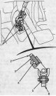
This area contains the Supplemental Restraint System (SRS) components. Review the SRS component locations, precautions, and procedures before performing repairs or maintenance. 1. combination switch; 2. Upper steering...
This area contains the Supplemental Restraint System (SRS) components. Review the SRS component locations, precautions, and procedures before performing repairs or maintenance. 1. combination switch; 2. Upper steering...
Steering column — removal and installation
1. Remove the driver's airbag assembly and coil wire. 2. Remove the steering wheel 3. Remove the lower instrument panel cover on the driver's side. 4. Remove the steering column covers ( drawing at the beginning of the...
1. Remove the driver's airbag assembly and coil wire. 2. Remove the steering wheel 3. Remove the lower instrument panel cover on the driver's side. 4. Remove the steering column covers ( drawing at the beginning of the...

Steering column — check
Check the steering column ball bearing and steering column joint bearings for play and smooth rotation. If there is noise or excessive play, replace the steering column assembly. Check if the retaining sleeve is...
Check the steering column ball bearing and steering column joint bearings for play and smooth rotation. If there is noise or excessive play, replace the steering column assembly. Check if the retaining sleeve is...

Replacing the steering column lock
1. Remove the steering column ( see above ). 2. Punch the two shear bolts and drill out their heads with a 5 mm drill. Be careful not to damage the switch housing when removing the shear bolts. 3. Remove the shear bolts...
1. Remove the steering column ( see above ). 2. Punch the two shear bolts and drill out their heads with a 5 mm drill. Be careful not to damage the switch housing when removing the shear bolts. 3. Remove the shear bolts...

Power Steering Hoses and Tubes
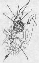
Checking for fluid leaks 1. HOSES and TUBES. Check hoses for damage, leaks, obstructions and kinks. Check the tubes for damage, rust and leaks. Check for leaks at the joints of hoses and tubes and at the fittings. 2....
Checking for fluid leaks 1. HOSES and TUBES. Check hoses for damage, leaks, obstructions and kinks. Check the tubes for damage, rust and leaks. Check for leaks at the joints of hoses and tubes and at the fittings. 2....
Power Steering Pump — Replacement
1. Place a suitable container under the vehicle. 2. Drain the power steering fluid from the reservoir. 3. Remove the belt by loosening the pump mounting bolt and lock bolt. 4. Cover the air conditioning compressor with...
1. Place a suitable container under the vehicle. 2. Drain the power steering fluid from the reservoir. 3. Remove the belt by loosening the pump mounting bolt and lock bolt. 4. Cover the air conditioning compressor with...

Power Steering Pump — Disassembly
Perform disassembly taking into account the following: The power steering components are made of aluminum. Do not damage them during assembly. Clean disassembled parts with solvent and dry with compressed air. Do not...
Perform disassembly taking into account the following: The power steering components are made of aluminum. Do not damage them during assembly. Clean disassembled parts with solvent and dry with compressed air. Do not...

Power Steering Pump — Check
Flow control valve 1. Inspect the flow control valve for wear, scoring or other damage to the edges of the grooves on the valve. 2. Check the flow control valve cylinder walls for scratches or wear. 3. Insert the valve...
Flow control valve 1. Inspect the flow control valve for wear, scoring or other damage to the edges of the grooves on the valve. 2. Check the flow control valve cylinder walls for scratches or wear. 3. Insert the valve...
Power Steering Pump — Assembly
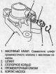
1. Align the intermediate valve pin with the oil channel in the pump body and press the intermediate valve in. Install the retaining ring. 2. Press the new pump seal by hand with the grooved side facing inward into the...
1. Align the intermediate valve pin with the oil channel in the pump body and press the intermediate valve in. Install the retaining ring. 2. Press the new pump seal by hand with the grooved side facing inward into the...

Steering gear — removal
Perform the removal taking into account the following: Using solvent and a brush, wash away oil and dirt from the valve body assembly, its tubes and the end of the steering gear. Blow with compressed air. Before...
Perform the removal taking into account the following: Using solvent and a brush, wash away oil and dirt from the valve body assembly, its tubes and the end of the steering gear. Blow with compressed air. Before...
Disassembling the steering rack
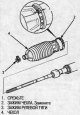
Perform disassembly taking into account the following: Before disassembling the steering gear, wash it with solvent and a brush. Do not wash seals and O-rings in solvent. 1. Remove the steering gear ( see above ). 2....
Perform disassembly taking into account the following: Before disassembling the steering gear, wash it with solvent and a brush. Do not wash seals and O-rings in solvent. 1. Remove the steering gear ( see above ). 2....

Disassembling the steering gear valve body
20. Before removing the valve body, wrap the worm shaft splines with vinyl tape. 21. Press the worm shaft/valve out of the valve body. 22. Check the inner wall in the valve body where the sealing ring slides by...
20. Before removing the valve body, wrap the worm shaft splines with vinyl tape. 21. Press the worm shaft/valve out of the valve body. 22. Check the inner wall in the valve body where the sealing ring slides by...
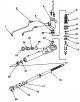
Steering gear — assembly
Perform the assembly taking into account the following: Clean disassembled parts with solvent and dry with compressed air. Do not wash rubber parts in solvent. Always replace O-rings and rubber seals with new ones...
Perform the assembly taking into account the following: Clean disassembled parts with solvent and dry with compressed air. Do not wash rubber parts in solvent. Always replace O-rings and rubber seals with new ones...
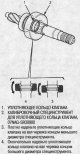
Steering gear valve body assembly
1. Apply grease to the ball bearing and use the special tool to press it onto the worm shaft. Then securely place the new ring clamp into the groove on the worm shaft. 2. Wrap the stepped portion of the worm shaft with...
1. Apply grease to the ball bearing and use the special tool to press it onto the worm shaft. Then securely place the new ring clamp into the groove on the worm shaft. 2. Wrap the stepped portion of the worm shaft with...

Steering rack assembly
25. Apply power steering fluid to the piston seal guide, then install it onto the rack with the large end first. 26. Place a new O-ring and a new piston seal ring on the special tool and push them onto the special tool...
25. Apply power steering fluid to the piston seal guide, then install it onto the rack with the large end first. 26. Place a new O-ring and a new piston seal ring on the special tool and push them onto the special tool...

Steering gear — installation
1. Install the support pads and mounting brackets on the steering gear as shown in the figure. Position the support pad B so that the dimension between mounting brackets A and B is as shown in the figure. 2. Before...
1. Install the support pads and mounting brackets on the steering gear as shown in the figure. Position the support pad B so that the dimension between mounting brackets A and B is as shown in the figure. 2. Before...

Replacing ball joint covers
1. Remove the boot from the tie rod end and wipe off the old grease from the ball joint. 2. Pack the lower portion of the ball joint with fresh grease. 1. EDGE 2. COVER INSTALLATION AREA. Wipe off the grease. 3. BALL...
1. Remove the boot from the tie rod end and wipe off the old grease from the ball joint. 2. Pack the lower portion of the ball joint with fresh grease. 1. EDGE 2. COVER INSTALLATION AREA. Wipe off the grease. 3. BALL...

Steering Specifications
Steering Specifications *: When installing a new belt, adjust the deflection or tension to the values for the new belt. Start the engine, let it run for 5 minutes and turn it off. Adjust the deflection or tension again...
Steering Specifications *: When installing a new belt, adjust the deflection or tension to the values for the new belt. Start the engine, let it run for 5 minutes and turn it off. Adjust the deflection or tension again...
This section is available on: russian, bulgarian, belarusian, ukrainian, serbian, croatian, romanian, polish, slovak, hungarian
Link in different formats to this section
TEXTHTMLBB Code
- General information
- User manual
- Maintenance
- Power unit
- Engine repair
- Lubrication system
- Cooling system
- Fuel injection and control
- Power and exhaust system
- Engine electrical equipment
- Transmission
- Clutch
- Mechanical gearbox
- Automatic gearbox
- Rear differential
- Drive shafts and cardan
- Chassis and running gear
- Steering
- Car suspension
- Brake system
- Body and interior
- Exterior (external elements)
- Interior (internal elements)
- Doors, locks and windows
- Electrical equipment
- Equipment and devices
- Lighting system
- Electrical circuits