


Car engine cooling system Honda HR-V 1

Engine cooling system — design description
Total capacity of the cooling system (including heater and reservoir): Manual transmission: 3.9 l CVT: 4.1L Tank capacity: 0.4 l Note: Check all cooling system hoses for damage, leaks or failure and replace if...
Total capacity of the cooling system (including heater and reservoir): Manual transmission: 3.9 l CVT: 4.1L Tank capacity: 0.4 l Note: Check all cooling system hoses for damage, leaks or failure and replace if...

Radiator of the cooling system — replacement
1. Drain the engine coolant. 2. Disconnect the upper and lower radiator hoses and ATF cooler hoses. 3. Disconnect the fan motor connector. 4. Remove the upper radiator bracket, then take out the radiator. 5. Remove the...
1. Drain the engine coolant. 2. Disconnect the upper and lower radiator hoses and ATF cooler hoses. 3. Disconnect the fan motor connector. 4. Remove the upper radiator bracket, then take out the radiator. 5. Remove the...

Filling with coolant and bleeding
1. Start the engine. Set the heater temperature control dial to the maximum heating position, then turn off the engine, make sure the engine and radiator are cool to the touch. 2. Remove the radiator cap. 3. Loosen the...
1. Start the engine. Set the heater temperature control dial to the maximum heating position, then turn off the engine, make sure the engine and radiator are cool to the touch. 2. Remove the radiator cap. 3. Loosen the...

Thermostat — Checking and Replacing
Replacement Note: When assembling, install new O-rings. 1. THERMOSTAT. Install with the pin facing up. 2. PIN 3. RUBBER SEAL. Replace. 4. THERMOSTAT COVER 5. 6x1.0 mm, 11 Nm (1.1 kgf/m) 6. O-RING, Replace. 7. RADIATOR...
Replacement Note: When assembling, install new O-rings. 1. THERMOSTAT. Install with the pin facing up. 2. PIN 3. RUBBER SEAL. Replace. 4. THERMOSTAT COVER 5. 6x1.0 mm, 11 Nm (1.1 kgf/m) 6. O-RING, Replace. 7. RADIATOR...

Water pump — design description
1. COOLANT TEMPERATURE GAUGE SENSOR, 9 Nm (0.9 kgf/m). Apply sealant to the threads. 2. 6x1.0 mm, 11 Nm (1.1 kgf/m) 3. WATER DRAINAGE PIPE COVER Apply sealant to the contact surface. 4. O-RING, Replace. 5. O-RING,...
1. COOLANT TEMPERATURE GAUGE SENSOR, 9 Nm (0.9 kgf/m). Apply sealant to the threads. 2. 6x1.0 mm, 11 Nm (1.1 kgf/m) 3. WATER DRAINAGE PIPE COVER Apply sealant to the contact surface. 4. O-RING, Replace. 5. O-RING,...

Water Pump — Checking and Replacing
Examination 1. Remove the timing belt. 2. Make sure the water pump rotates counterclockwise. 3. Check for signs of leakage through the seal. Note: A slight leak from the bleed nipple is considered normal. Replacement 1....
Examination 1. Remove the timing belt. 2. Make sure the water pump rotates counterclockwise. 3. Check for signs of leakage through the seal. Note: A slight leak from the bleed nipple is considered normal. Replacement 1....
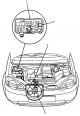
Fan — component layout and wiring diagram
Component arrangement: 1. Fuse/relay box under the hood 2. Radiator fan relay. 3. Radiator Fan Switch. Testing ( see below ) 4. Radiator Fan Motor Testing ( see below )
Component arrangement: 1. Fuse/relay box under the hood 2. Radiator fan relay. 3. Radiator Fan Switch. Testing ( see below ) 4. Radiator Fan Motor Testing ( see below )
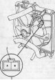
Testing the Fan Motor
1. Disconnect the 2-pin connectors from the radiator fan motor. 1. Radiator fan motor 2. Stopper 3. Male connector on the contacts side 2. Test the motor by applying battery power to terminal B and grounding terminal A....
1. Disconnect the 2-pin connectors from the radiator fan motor. 1. Radiator fan motor 2. Stopper 3. Male connector on the contacts side 2. Test the motor by applying battery power to terminal B and grounding terminal A....

Testing the Radiator Fan Switch
Note: After installing the radiator fan switch, bleed the cooling system ( see above ). 1. Remove the radiator fan switch from the thermostat cover. 2. Hang the radiator fan switch in a container of water as shown in...
Note: After installing the radiator fan switch, bleed the cooling system ( see above ). 1. Remove the radiator fan switch from the thermostat cover. 2. Hang the radiator fan switch in a container of water as shown in...
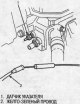
Engine coolant temperature gauge
Testing the pointer 1. Before testing, check fuse #6 (7.5A) in the fuse/relay box under the instrument panel on the driver's side. 2. Make sure the ignition switch is in the OFF position, then disconnect the...
Testing the pointer 1. Before testing, check fuse #6 (7.5A) in the fuse/relay box under the instrument panel on the driver's side. 2. Make sure the ignition switch is in the OFF position, then disconnect the...

This section is available on: russian, bulgarian, belarusian, ukrainian, serbian, croatian, romanian, polish, slovak, hungarian
Link in different formats to this section
TEXTHTMLBB Code
- General information
- User manual
- Maintenance
- Power unit
- Engine repair
- Lubrication system
- Cooling system
- Fuel injection and control
- Power and exhaust system
- Engine electrical equipment
- Transmission
- Clutch
- Mechanical gearbox
- Automatic gearbox
- Rear differential
- Drive shafts and cardan
- Chassis and running gear
- Steering
- Car suspension
- Brake system
- Body and interior
- Exterior (external elements)
- Interior (internal elements)
- Doors, locks and windows
- Electrical equipment
- Equipment and devices
- Lighting system
- Electrical circuits