
Fluid Leak Test
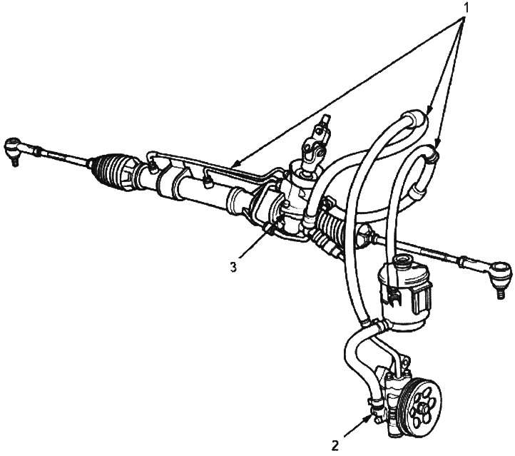
1. HOSES and PIPES.
Check hoses for damage, leakage, obstruction and kinks.
Check tubing for damage, rust and leakage.
Check for leaks at the joints of hoses and tubes and fittings.
2. PUMP ASSEMBLY.
Check for leakage at the pump seal, inlet and outlet fittings.
3. STEERING GEAR AND VALVE BODY ASSEMBLY
Check for leakage from contact surfaces and flare nuts.
Replacement
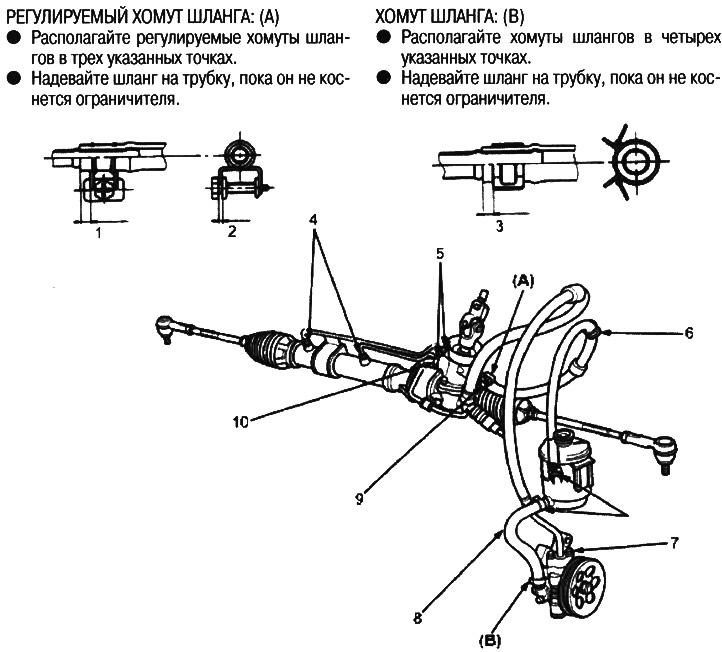
1. 2.5-5.5mm
2. 2.0-4.0mm
3. 2.5-5.5mm
4. CYLINDER PIPE TO CYLINDER, 24 Nm (2.4 kgf/m)
5. CYLINDER PIPE TO VALVE BODY ASSEMBLY, 20 Nm (2.0 kgf/m)
6. OUTLET HOSE
7. PUMP SUPPLY PIPE 6x1.0 mm, 11 Nm (1.1 kgf/m)
8. SUPPLY HOSE
9. OUTLET PIPE CONNECTION 16x1.5 mm, 28 Nm (2.9 kgf/m)
10. SUPPLY PIPE 14x1.5 mm, 37 Nm (3.8 kgf/m)
Perform installation with the following in mind:
- Connect the hoses to the tubes securely until the hose rests against the stopper on the tube. Attach the clamp or adjustable clamp at the specified distance from the end of the hose, as shown in the illustration.
- Check all clamps for wear or deformation; replace with new clamps if necessary.
- Add the recommended power steering fluid to the correct level on the reservoir and check for leakage.