


Vehicle car suspension Honda HR-V 1

Location of suspension components
Front suspension 1. front wheel shock absorber; 2. steering knuckle; 3. lower arm; 4. Front stabilizer bar Rear suspension 1. rear wheel shock absorber; 2. spring; 3. lower pull; 4. Upper pull; 5. rear stabilizer bar;...
Front suspension 1. front wheel shock absorber; 2. steering knuckle; 3. lower arm; 4. Front stabilizer bar Rear suspension 1. rear wheel shock absorber; 2. spring; 3. lower pull; 4. Upper pull; 5. rear stabilizer bar;...

Wheel alignment angles
Service information Note: Before performing a proper wheel alignment check/adjustment, perform the following checks and adjustments: Make sure that no modifications have been made to the suspension. Check the tire size...
Service information Note: Before performing a proper wheel alignment check/adjustment, perform the following checks and adjustments: Make sure that no modifications have been made to the suspension. Check the tire size...

Checking wheel alignment
1. Remove the wheel cap. 2. Remove the cap from the rear wheel hub ( see further ). 3. Install the wheel alignment tool and the front camber and caster angle measuring device onto the wheel hub. 4. Set the front wheels...
1. Remove the wheel cap. 2. Remove the cap from the rear wheel hub ( see further ). 3. Install the wheel alignment tool and the front camber and caster angle measuring device onto the wheel hub. 4. Set the front wheels...

Longitudinal tilt of the pivot axis — check
1. Remove the wheel cap. 2. Raise the car and place the steering angle measuring stands under the front wheels, and place boards of the same thickness as the stands under the rear wheels, then lower the car. Note: Make...
1. Remove the wheel cap. 2. Raise the car and place the steering angle measuring stands under the front wheels, and place boards of the same thickness as the stands under the rear wheels, then lower the car. Note: Make...

Checking and adjusting the alignment
Examination 1. Center the steering wheel spokes. Note: Measure the difference in toe-in measurements in the straight-ahead position of the road wheels. 2. Check the front toe-in. Front toe-in: 0±3 mm. If adjustment is...
Examination 1. Center the steering wheel spokes. Note: Measure the difference in toe-in measurements in the straight-ahead position of the road wheels. 2. Check the front toe-in. Front toe-in: 0±3 mm. If adjustment is...

Checking the wheel runout
1. Raise the vehicle with four wheels off the ground and securely support it on the safety stands at the designated points. 2. Check for bent or deformed wheels. 3. Fix the indicator as shown in the pictures on the...
1. Raise the vehicle with four wheels off the ground and securely support it on the safety stands at the designated points. 2. Check for bent or deformed wheels. 3. Fix the indicator as shown in the pictures on the...

Replacing the front suspension arms
Perform the replacement taking into account the following: After removal, replace the self-locking nuts. The vehicle must be lowered to the ground before tightening the bolts or nuts on the rubber mounts or bushings....
Perform the replacement taking into account the following: After removal, replace the self-locking nuts. The vehicle must be lowered to the ground before tightening the bolts or nuts on the rubber mounts or bushings....
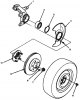
Replacing the steering knuckle and hub
Perform the replacement taking into account the following: Use only genuine Honda aluminum wheel weights. Non-genuine weights may cause corrosion and damage to aluminum wheels. Remove the center cap from the inside of...
Perform the replacement taking into account the following: Use only genuine Honda aluminum wheel weights. Non-genuine weights may cause corrosion and damage to aluminum wheels. Remove the center cap from the inside of...

Replacing the ball joint boot
Caution: Do not contaminate the area where the cover is installed with grease. 1. Remove the boot from the lower arm and wipe off the old grease from the ball joint. 2. Pack the lower portion of the ball joint with...
Caution: Do not contaminate the area where the cover is installed with grease. 1. Remove the boot from the lower arm and wipe off the old grease from the ball joint. 2. Pack the lower portion of the ball joint with...

Front shock absorber — removal
1. Remove the front wheels. 2. Remove the wheel sensor wire from the steering knuckle and shock absorber. Do not disconnect the wheel sensor connector. 3. Separate the stabilizer bar from the lower arm ( see above ). 4....
1. Remove the front wheels. 2. Remove the wheel sensor wire from the steering knuckle and shock absorber. Do not disconnect the wheel sensor connector. 3. Separate the stabilizer bar from the lower arm ( see above ). 4....

Front shock absorber — disassembly
1. Compress the shock absorber spring with a spring compressor according to the manufacturer's instructions. Do not compress the spring more than necessary. 1. STRUT SPRING COMPRESSOR (commercially available) BRANICK(c)...
1. Compress the shock absorber spring with a spring compressor according to the manufacturer's instructions. Do not compress the spring more than necessary. 1. STRUT SPRING COMPRESSOR (commercially available) BRANICK(c)...

Front shock absorber — check
1. Assemble all parts except the spring. 2. Press the shock absorber assembly as shown in the figure. 1. Wooden block 3. Check for smooth operation along the entire stroke, both when compressed and when extended. The...
1. Assemble all parts except the spring. 2. Press the shock absorber assembly as shown in the figure. 1. Wooden block 3. Check for smooth operation along the entire stroke, both when compressed and when extended. The...

Front shock absorber — assembly
1. Insert the shock absorber assembly into the spring compressor. 2. Reassemble the shock absorber in the reverse order of disassembly, except for the shock absorber washer and self-locking nut. Align the bottom of the...
1. Insert the shock absorber assembly into the spring compressor. 2. Reassemble the shock absorber in the reverse order of disassembly, except for the shock absorber washer and self-locking nut. Align the bottom of the...

Front shock absorber — installation
1. Place the shock absorber onto the frame with the alignment tab facing inward, then install the flange nuts. 1. NUT WITH SHELL, 10x1.25 mm, 69 Nm (7.0 kgf/m) 2. COMBINATION PROJECTION 2. Insert the shock absorber into...
1. Place the shock absorber onto the frame with the alignment tab facing inward, then install the flange nuts. 1. NUT WITH SHELL, 10x1.25 mm, 69 Nm (7.0 kgf/m) 2. COMBINATION PROJECTION 2. Insert the shock absorber into...
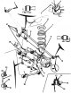
Replacing the rear suspension arms
Perform the replacement taking into account the following: After removal, replace the self-locking nuts. The vehicle must be lowered to the ground before tightening the bolts or nuts on the rubber mounts or bushings....
Perform the replacement taking into account the following: After removal, replace the self-locking nuts. The vehicle must be lowered to the ground before tightening the bolts or nuts on the rubber mounts or bushings....
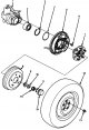
Rear Wheel Bearing — Replacement
Perform the replacement taking into account the following: Use only genuine Honda aluminum wheel weights. Non-genuine weights may cause corrosion and damage to aluminum wheels. Before installing the brake drum, clean...
Perform the replacement taking into account the following: Use only genuine Honda aluminum wheel weights. Non-genuine weights may cause corrosion and damage to aluminum wheels. Before installing the brake drum, clean...

Spring, rear shock absorber limiter
Removal 1. Raise the rear of the vehicle and support it securely. Remove the rear wheel. 2. Remove the flange bolt from the rear axle beam. 3. Unscrew the 10 mm self-locking nut and separate the stabilizer rod from the...
Removal 1. Raise the rear of the vehicle and support it securely. Remove the rear wheel. 2. Remove the flange bolt from the rear axle beam. 3. Unscrew the 10 mm self-locking nut and separate the stabilizer rod from the...

Rear shock absorber — removal, inspection and installation
1. Raise the rear of the vehicle and support it securely. Remove the rear wheel. 2. Remove the flange bolt from the rear axle beam. 1. REAR SHOCK ABSORBER 2. REAR AXLE BEAM 3. BOLT WITH FLANGE, 10x1.25 mm 3. Remove the...
1. Raise the rear of the vehicle and support it securely. Remove the rear wheel. 2. Remove the flange bolt from the rear axle beam. 1. REAR SHOCK ABSORBER 2. REAR AXLE BEAM 3. BOLT WITH FLANGE, 10x1.25 mm 3. Remove the...

Disposal of shock absorbers
The shock absorbers contain nitrogen gas and oil under pressure. To avoid explosion and possible injury, pressure must be released before disposal. Place the shock absorber on a flat surface with the end of the rod...
The shock absorbers contain nitrogen gas and oil under pressure. To avoid explosion and possible injury, pressure must be released before disposal. Place the shock absorber on a flat surface with the end of the rod...

This section is available on: russian, bulgarian, belarusian, ukrainian, serbian, croatian, romanian, polish, slovak, hungarian
Link in different formats to this section
TEXTHTMLBB Code
- General information
- User manual
- Maintenance
- Power unit
- Engine repair
- Lubrication system
- Cooling system
- Fuel injection and control
- Power and exhaust system
- Engine electrical equipment
- Transmission
- Clutch
- Mechanical gearbox
- Automatic gearbox
- Rear differential
- Drive shafts and cardan
- Chassis and running gear
- Steering
- Car suspension
- Brake system
- Body and interior
- Exterior (external elements)
- Interior (internal elements)
- Doors, locks and windows
- Electrical equipment
- Equipment and devices
- Lighting system
- Electrical circuits