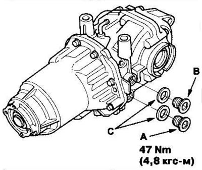
Rear differential assembly
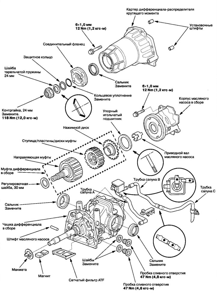
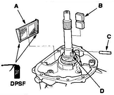
1. Apply DPSF fluid to the ATF strainer rubber (A), then install the ATF strainer, magnet (B), oil pump pin (C) and seal (D) to the differential cup assembly.
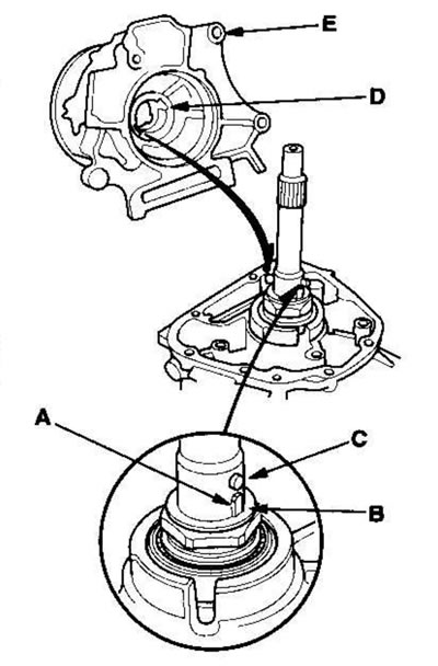
2. Align the tabs (A) of the seal (B) with the oil pump pin (C). Align the grooves (D) on the rear oil pump with the oil pump pin and the tabs of the seal, then install the oil pump housing assembly (E) onto the differential carrier assembly.
3. Tighten the oil pump housing assembly mounting bolts.
4. Install the oil pump drive shaft (A) by aligning the tab (B) on the oil pump drive shaft with the groove on the front oil pump in the oil pump housing assembly.
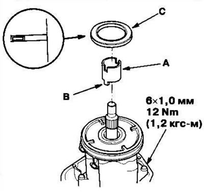
5. Install the thrust needle bearing (C).
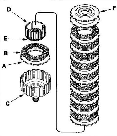
6. If necessary, assemble the differential clutch, following these steps:
- Place one metal plate (A) and one felt disc (B) into the coupling guide (C), then the hub with the snap ring (D).
- Make sure the splines on the clutch hub and felt disc align under the snap ring (E).
- Alternately place the remaining metal plates and felt discs until you count eleven plates and ten discs, then place the pressure disc (F).
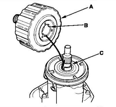
7. Install the differential clutch assembly (A) by aligning the tabs on the pressure plate (B) with the grooves on the oil pump drive shaft (C). Tighten the eight mounting bolts in a crisscross pattern in several passes.
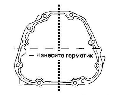
8. Remove dirt and oil from the sealing surfaces. Apply sealant (08X70-K0234M) onto the sealing surface. To prevent oil leakage, seal the bolt holes around their entire circumference.
Note:
- If more than 5 minutes have passed since applying the sealant, apply it again and reassemble the crankcases.
- Allow the sealant to cure for at least 20 minutes after assembly before filling the differential with oil.
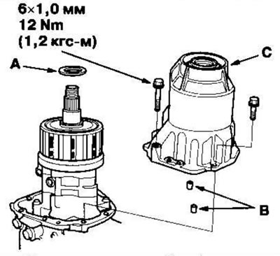
9. Install the 30 mm adjusting washer (A), 6 x 1.0 mm dowel pins (B) and torque distribution differential housing (C). Tighten the eight mounting bolts in a crisscross pattern in several passes.
10. Install the connecting flange (A), O-ring (B), protective ring (C), disc spring washer (D) and locknut (E).
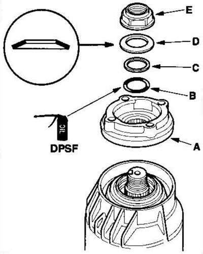
Note: Apply DPSF fluid to the O-ring.
11. Install the special tool on the connecting flange, then tighten the new lock nut to the required torque.
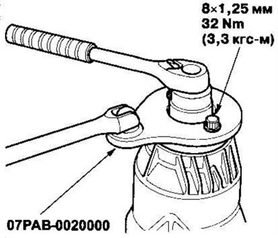
Tightening torque: 118 Nm (12.0 kgf·m)
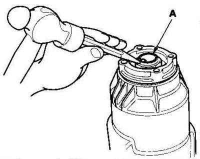
12. Press the tongue of the lock nut (A) into the groove of the guide sleeve.
13. Screw the plug (A) into the drain hole and the plug (B) into the filler hole, installing new sealing washers (C).