
2. Press the switch "AUTO" and, without releasing it, on the switch "OFF" air conditioning and heater control panels.
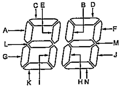
3. By turning on the sectors of the temperature indicator, determine the malfunction.
Note:
- If there are no faults, the temperature gauge will not turn on.
- In the event of a malfunction, alternately (at intervals of 1 second) all sectors of the temperature indicator and sectors indicating malfunctions will light up.
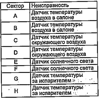
- Simultaneous presence of faults "A", "WITH", "E", "G", "I", "L" may indicate an open circuit in the common ground of the sensors (see table "Air conditioning system malfunctions").
4. To complete the test, turn off the ignition.
5. After repairing or replacing defective components, recheck.
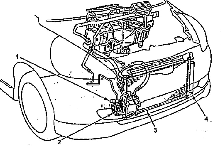
The location of the components.
1 - pressure switch,
2 - compressor assembly,
3 - capacitor,
4 - dryer.
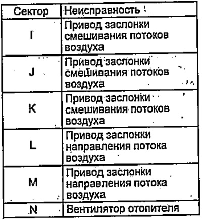
Table. Air conditioning system malfunctions.
 |  |
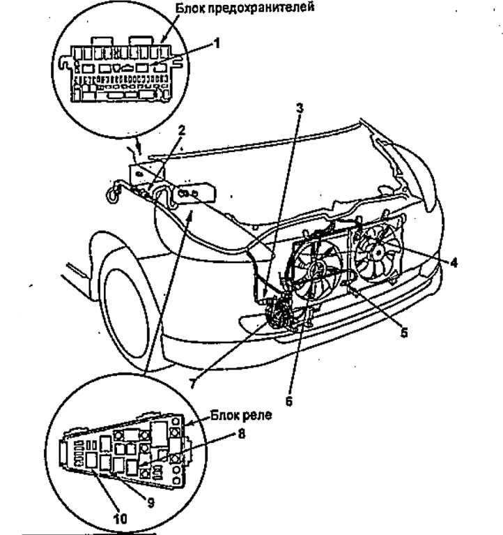
Location of components (continuation).
1 - heater fan motor relay,
2 - noise suppressor,
3 - pressure switch,
4 - connector of the electric motor of the fan of the cooling system,
5 - ambient temperature sensor,
6 - condenser fan motor connector;
7 - connector for the electromagnetic clutch of the air conditioning compressor,
8 - relay of the electric motor of the fan of the cooling system,
9 - condenser fan motor relay,
10 - relay of the electromagnetic clutch of the compressor. air conditioner.
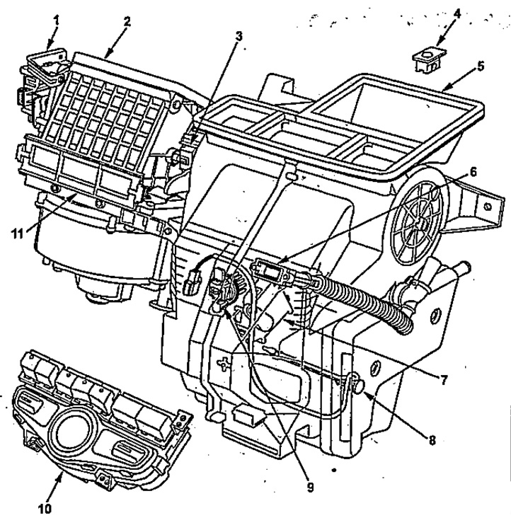
Location of components (continuation).
1 - air intake damper drive,
2 - heater fan unit,
3 - damper drive for air flow direction,
4 - sunlight sensor,
5 - heater and air conditioner unit,
6 - air temperature sensor in the cabin,
7 - damper drive for mixing air flows,
8 - temperature sensor behind the evaporator,
9 - power transistor,
10 - control panel for air conditioning and heater.
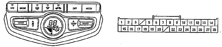
Control panel for air conditioning and heater.