
2. Turn the ignition key to position "ON".
3. Measure voltage between terminal #3 of the solenoid clutch connector and ground.
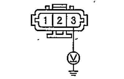
If the voltage is approximately 5 V, then proceed to step No. 4, if the voltage is greater or less, check the integrity of the connector of the electronic control unit for the injection system and the integrity of the wiring harness between the air conditioning compressor and the electronic control unit for the injection system. If the ECU connector is good and there is no open in the wiring harness, the ECU may need to be replaced.
4. Turn the ignition key to position "OFF".
5. Check the thermal fuse. If the thermal fuse is good, proceed to step #6. If the thermal fuse is defective, replace it.
6. Connect the electromagnetic clutch connector.
7. Disconnect the pressure switch.
8. Turn the ignition key to position "ON".
9. Measure the voltage between pin #2 of the pressure switch connector and ground.
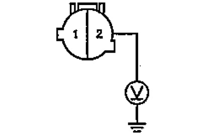
If the voltage is approximately 5 V, proceed to step No. 10, if the voltage is greater or less, then an open in the drive harness between the suppression switch and the thermal fuse should be repaired.
10. Turn the ignition key to position "OFF".
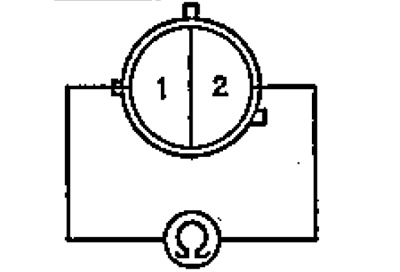
11. Check for continuity between pin #1 and pin #2 of the pressure switch connector. If there is continuity, go to step #12, if there is no conductivity, go to step #34.
12. Connect the pressure switch connector.
13. Disconnect the A/C switch connector.
14. Turn the ignition key to position "ON".
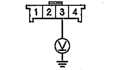
15. Measure the voltage between terminal #8 of the A/C switch connector and ground.

If the voltage is approximately 5 V, proceed to step No. 16, if the voltage is greater or less, repair an open in the wire circuit between the air conditioner switch and the pressure switch.
16. Turn the ignition key to position "OFF".
17. Check up serviceability of the switch of the conditioner. If the air conditioner switch is OK, proceed to step No. 18, if not, it should be replaced.
18. Disconnect the airflow direction switch connector.
19. Turn the ignition key to position "ON".
20. Measure the voltage between terminal #3 of the airflow direction switch and ground.
If the voltage is approximately 5 V, proceed to step #21, if the voltage is more or less, repair an open in the wire circuit between the pressure switch and the air flow direction switch.
21. Turn the ignition key to position "OFF".
22. Check the air flow direction switches, if the switch is OK, proceed to step No. 23, if the switch is faulty, it may be necessary to replace the air conditioning and heater control panel.
23. Disconnect the heater fan speed-rotation switch connector.
24. Check up conductivity between an output No. 7 of a socket of the switch to conditioners an output No. 6 of a socket of the switch of speed of rotation of the fan of a heater.
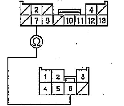
If continuity is present, proceed to step #25, if there is no continuity, repair an open in the wire circuit between the A/C switch and the heater fan speed switch.
25. Check continuity between terminal #4 of the air flow direction switch connector and terminal #6 of the heater fan speed switch connector.
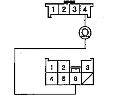
If continuity is present, then proceed to step #26, if there is no conductivity, repair the open in the wire circuit between the switches.
26. Check the heater fan speed switch. If the switch is OK, proceed to step #27, if the switch is faulty, it should be replaced.
27. Check continuity between Terminal #3 of heater fan speed switch and ground.
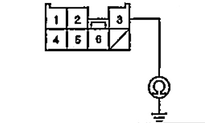
If there is continuity, then proceed to step No. 28, if there is no conductivity, repair a possible open in the circuit between the heater fan speed switch and ground, check the ground wire G402.
28. Disconnect the temperature sensor connector behind the evaporator.
29. Measure the resistance between the terminals of the temperature sensor connector behind the evaporator.
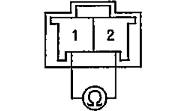
Verify that as the temperature changes, the resistance between the leads changes according to the graph.
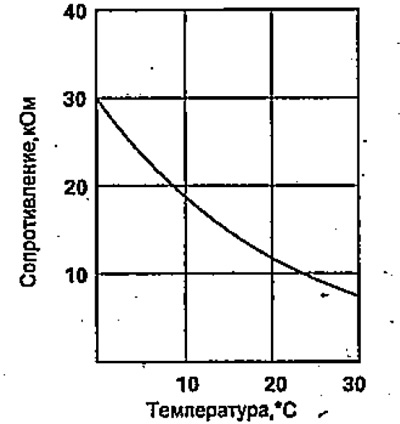
If the resistance corresponds to the graph, then proceed to step No. 30, if it does not match, then the temperature sensor behind the evaporator should be replaced.
30. Disconnect the SCS line with a tester.
31. Disconnect the connector of the electronic control unit for the injection system.
32. Check up conductivity between conclusions of a socket of the gauge of the temperature behind the evaporator and conclusions of a socket of the electronic block of management of injection system, as it is shown in drawing.
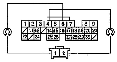
If there is continuity, proceed to step #33, if not, repair the open in the circuit between the temperature sensor behind the evaporator and the electronic control unit for the injection system.
33. Check up conductivity between an output of a socket of the electronic block of management of injection system and weight.
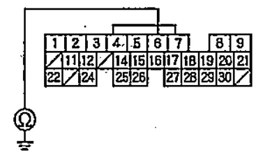
If there is continuity, repair the short to ground in the circuit between the temperature sensor - downstream of the evaporator and the ECM. If there is no continuity, check the reliability of the connectors of the electronic control unit for the injection system, the temperature sensor behind the evaporator, the suppression switch, the air conditioner switch. If all connectors are OK, replace the ECU with a good one and check again. If, after replacement, the symptoms of malfunctions have disappeared, the electronic control unit for the injection system should be replaced.
34. Verify that system pressure is within tolerance. If the pressure is normal, replace the pressure switch, if the pressure is higher or lower than normal, the cause of the pressure deterioration should be eliminated.