
2. Turn the ignition key to position "ON".
3. Measure the voltage between the pin "2" pressure and ground switch connector.
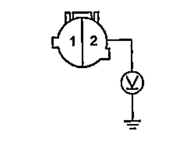
If the voltage is 4.30-5.25 V, proceed to step No. 5, if the voltage is more or less, then proceed to step No. 4.
4. Measure the voltage between the terminal "28" connector of the electronic control unit for the injection system and mass.
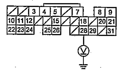
If the voltage is 4.30 - 5.25 V, repair the open circuit in the wires between the pressure switch and the electronic injection system control unit, if the voltage is more or less, install a working electronic injection system control unit and diagnose again.
5. Turn the ignition key to position "OFF".
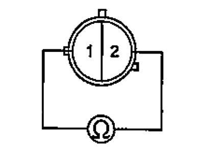
6. Check continuity between terminals "1" And "2" pressure switch connector. If there is continuity, proceed to step #7, if there is no continuity, the pressure switch should be replaced.
7. Connect the mute switch connector.
8. Disconnect the A/C switch connector.
9. Turn the ignition key to position "ON".
10. Measure the voltage between the terminal "2" air conditioner switch and ground.
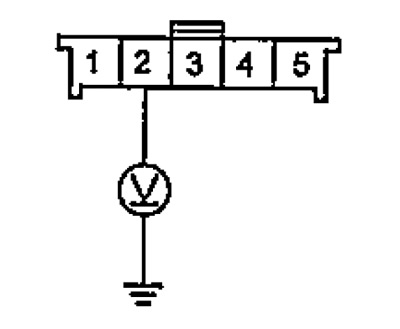
If the voltage is approximately 4.30 - 5.25 V, proceed to step No. 11, if the voltage is greater or less, repair an open in the wire circuit between the pressure switch and the air conditioner switch.
11. Turn the ignition key to position "OFF".
12. Remove the air conditioner switch. If the air conditioner switch is OK, proceed to step #13, if the air conditioner switch is defective, it should be replaced.
13. Disconnect the heater fan speed switch connector.
14. Check the continuity between the output "1" air conditioner switch connector output "6" heater fan speed switch.
If continuity is present, proceed to step #15, if there is no continuity, repair open in the wire circuit between the heater fan speed switch and the air conditioner switch.
15. Remove and check the heater fan speed switch. If the switch is OK, proceed to step #16, if it is faulty, it should be replaced.
16. Disconnect the temperature sensor connector behind the evaporator,
17. Place the temperature sensor behind the evaporator in the water and, by changing the temperature of the water, measure the resistance between the terminals "1" And "2" temperature sensor connector behind the evaporator. Verify that the temperature sensor downstream of the evaporator is changing according to the graph.
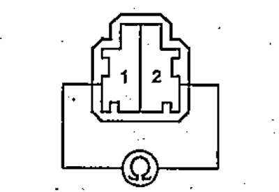 | 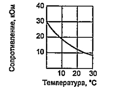 |
If the resistance changes with temperature according to the graph, proceed to step #18, if not, replace the temperature sensor behind the evaporator.
18. Disconnect the connector of the electronic control unit for the injection system.
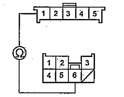
19. Make sure that there is continuity between the terminals of the connectors of the temperature sensor behind the evaporator and the electronic control unit for the injection system.
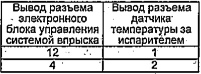 | 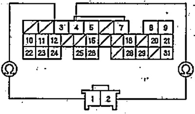 |
If there is continuity between the terminals, proceed to step No. 20, if there is no conductivity, eliminate the open in the wire circuit between the electronic control unit for the injection system and the temperature sensor behind the evaporator.
20. Check continuity between pin 12" connector of the electronic control unit for the injection system and mass.
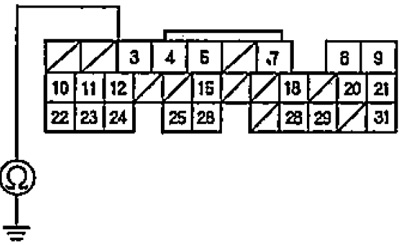
If there is continuity, repair short to ground in the circuit between the downstream evaporator temperature sensor and the ECM. If there is no continuity, check the reliability of the connectors of the electronic control unit for the injection system / temperature sensor behind the evaporator, pressure switch, air conditioning switch. If all connectors are OK, substitute a known-good ECM and test again. If, after replacement, the symptoms of malfunctions have disappeared, the electronic control unit for the injection system should be replaced.