
HondaBook.ru
Auto companies Volkswagen Auto companies Ford Auto companies Lada Auto companies Skoda Auto companies BMW Auto companies Mazda Auto companies Peugeot
English Русский
Български
Беларускі
Український
Српски
Hrvatski
Română
Polski
Slovenský
Magyar
Bookmark Contacts Sitemap   


Accord Civic Fit / Jazz CR-V HR-V Others Articles
CR-V 1 (1995-2001, petrol) CR-V 2 (2002-2006, petrol)

Assembling the rear drive shafts (Honda CR-V 2)

  • Main
  • Honda CR-V
  • 2 (2002-2006, petrol)
  • Transmission
  • Drive shafts
  • Assembling the rear drive shafts
0
Note: When assembling, please refer to the exploded view image.


Rear drive shafts (disassembled)
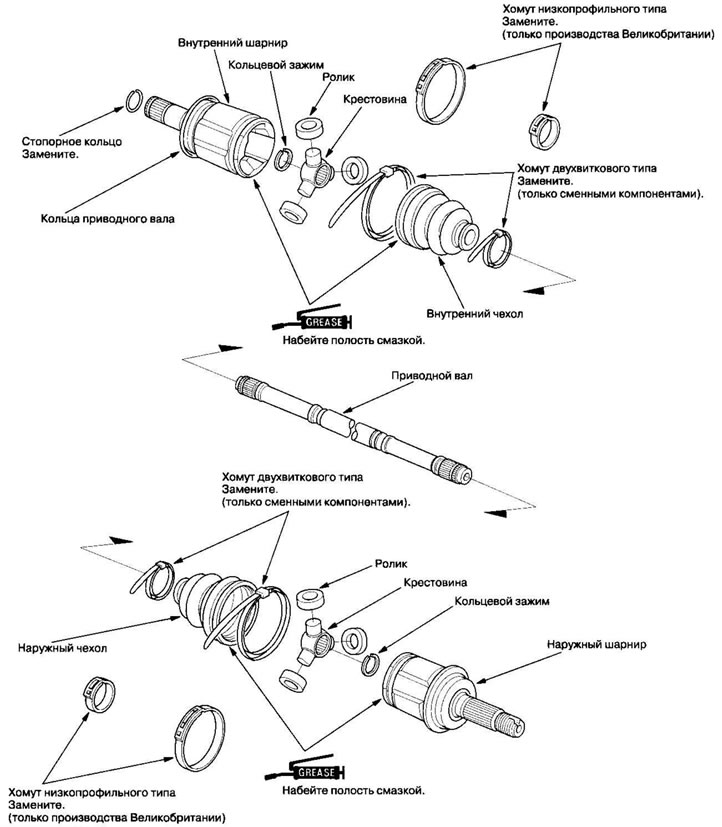


Rear drive shafts (disassembled)


1. To prevent damage to the inner boot, wrap the drive shaft splines with vinyl tape (A).
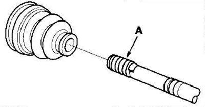
1. To prevent damage to the inner boot, wrap the…


2. Install the inner boot onto the drive shaft, then remove the vinyl tape. Do not damage the inner cover.

3. Install the crosspiece (A) onto the drive shaft, aligning the marks (B) on the crosspiece and on the end of the drive shaft.
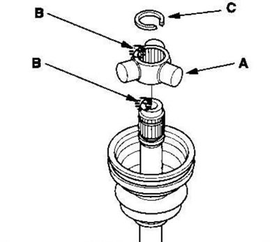
3. Install the crosspiece (A) onto the drive…


4. Place the ring clamp (C) into the groove on the drive shaft. To fully seat the ring clamp in the groove, rotate it.


5. Place the rollers (A) on the crosspiece (B) with the shoulders facing outward, taking into account the following:
  • Install the rollers in their original position on the crosspiece, aligning the marks (C).
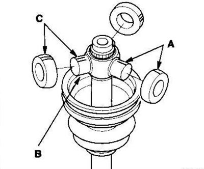
Install the rollers in their original position on…

  • To prevent the rollers from falling off, hold the drive shaft vertically.

6. Pack the inner joint with the joint grease supplied with the new drive shaft.
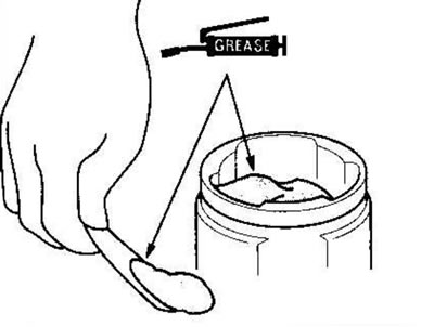
6. Pack the inner joint with the joint grease…


Amount of grease; inner hinge: 80-90 g

7. Place the inner joint onto the drive shaft, taking into account the following:
  • Install the inner joint onto the drive shaft, aligning the marks (A) on the inner joint and rollers.

  • Install the inner joint onto the drive shaft,…


  • To prevent the inner joint from falling off, hold the drive shaft vertically.
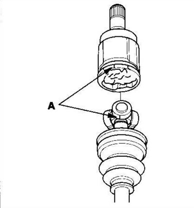
8. Adjust the length of the drive shafts as shown in the figure below, then set the boots midway between the fully compressed and fully retracted positions. Make sure the ends of the boots fit into the grooves of the drive shaft and hinge.
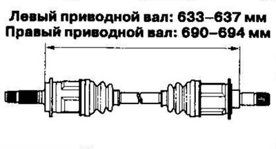


8. Adjust the length of the drive shafts as shown…


9. Make sure the ends of the boots fit into the grooves of the drive shaft and joint, then place the clamps on the boots.
  • If the clamps are of the two-turn type, proceed to step. 13. (Replacement cover clamps only)
  • If the clamps are low-profile type, proceed to step. 10. (UK made only)

10. Place the new low profile clamp (A) onto the boot (B), then hook it onto the tab (C) on the clamp.
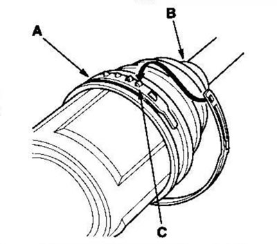
10. Place the new low profile clamp (A) onto the…


11. Compress the slit portion of the clamp using pliers (A) (available for sale), then hook onto the tabs (B) on the clamp.
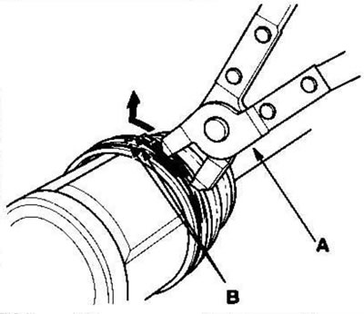
11. Compress the slit portion of the clamp using…


12. Put the clamp on the other side of the cover and repeat steps. 10 and 11.


13. Insert the ends of the boot into the grooves on the drive shaft and joint, then place a new two-turn type clamp (A) onto the boot.
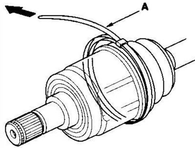
13. Insert the ends of the boot into the grooves…


14. Remove any slack in the clamp by hand.

15. Place a mark (A) on the clamp 10-14 mm from the bracket (B).
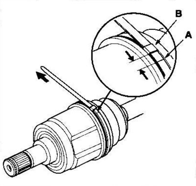
15. Place a mark (A) on the clamp 10-14 mm from…


16. Pass the free end of the clamp tape through the nose of the special tool for tightening the clamps of the covers KD-3191 (available for sale) or equivalent (A) and into a slot on the rotating mandrel (B).
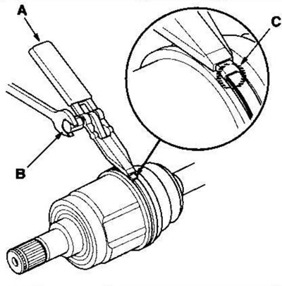
16. Pass the free end of the clamp tape through…


17. Place the wrench on the rotating mandrel of the special tool and tighten the clamp until the mark (C) on the band reaches the edge of the bracket.


18. Raise the special tool and bend the free end of the clamp band at an angle of 90° to the bracket. Mark the bracket with a center punch, then wrap the tip onto the bracket.
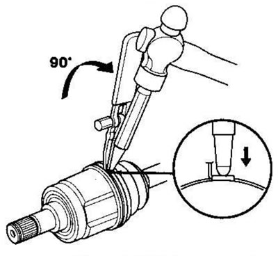
18. Raise the special tool and bend the free end…


19. Release the special tool mandrel and trim off the excess tape, leaving a 5-10 mm tip protruding from the bracket.
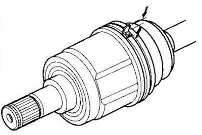
19. Release the special tool mandrel and trim off…


20. Bend the end of the tape (A) by tapping it with a hammer.
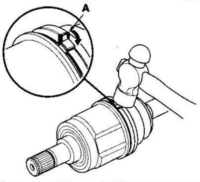
20. Bend the end of the tape (A) by tapping it…


Note:
  • Make sure that the tape and clamp do not touch anything and that the tape does not move.
  • Remove excess grease from adjacent areas.


21. Install a new retaining ring (A).
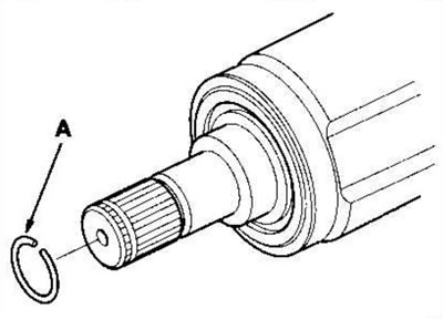
21. Install a new retaining ring (A).


The text of the article is available on the website: www.HondaBook.ru
This article is available at: russian, bulgarian, belarusian, ukrainian, serbian, croatian, romanian, polish, slovak, hungarian
This information has been verified: Mikhail Kopasov
Share with friends:
◀ Previous
CR-V 2: Drive shafts
Next ▶

Disassembling the rear drive shafts
Removal the rear drive shafts
Installing the intermediate shaft
Assembling the intermediate shaft
Disassembling the intermediate shaft
Installing rear drive shafts
Checking the cardan shaft
Removal the propeller shaft
Installing the cardan shaft
See also other articles from Honda manuals:
Removal and installation drive shafts Honda Accord 6 (1997-2002)
Rear Drive Axles (1988 and later models) — Removal, Repair and… Honda Civic 3 and 4 (1983-1991)
Rear Drive Shafts — Removal Honda Fit 1 (2001-2008)
Description of the design of the rear drive shafts Honda HR-V 1 (1998-2006, petrol)
Rear Drive Shafts (4WD Models) — Removal Honda Avancier 1 (1999-2003, petrol)
Link in different formats to this article
Comments and feedback from visitors
No comments yet


How much will 40 + 33 ?


CR-V 2 (2002-2006, petrol) 
  • General information
  • User manual
  • Technical data
  • Maintenance
  • Power unit
  • Engine repair
  • Lubrication system
  • Cooling system
  • Exhaust system
  • Fuel system
  • Engine management
  • Engine electrical equipment
  • Transmission
  • Clutch
  • Manual gearbox
  • Automatic gearbox
  • Rear differential
  • Drive shafts
  • Chassis and running gear
  • Steering
  • Front suspension
  • Rear suspension
  • Brake system
  • Body and interior
  • Exterior (external elements)
  • Interior (internal elements)
  • Doors, locks and windows
CR-V 1 (1995-2001, petrol) 
  • General information
  • Maintenance
  • Tips for car owner
  • Power unit
  • Engine repair
  • Engine overhaul
  • Cooling and lubrication system
  • Engine electrical equipment
  • Control system
  • Fuel system
  • Transmission
  • Clutch and drive shafts
  • Car gearbox
  • Chassis and running gear
  • Front suspension
  • Rear suspension
  • Steering
  • Brake system
  • Body and interior
  • Body service
  • Exterior (external elements)
  • Interior (internal elements)
  • Electrical equipment
  • Equipment and devices
  • Electrical circuits
HondaBook.ru © 2018–2026 • Mobile version • Sitemap: EN BG BY UA RS HR RO PL SK HU • Feedback • Driver Information • Search system • Bookmark
Accord 3 (1985-1989) • Accord 6 (1997-2002) • Civic 3 and 4 (1983-1991) • Civic 5 and 6 (1991-2000) • Civic 6 (1995-2000) • Civic 7 (2000-2005) • Civic 8 (2005-2011) • Fit 1 (2001-2008) • CR-V 1 (1995-2001) • CR-V 2 (2002-2006) • HR-V 1 (1998-2006) • Avancier 1 (1999-2003) •
 
This website uses cookies to ensure proper functioning. By clicking "OK," you agree.