
Pump disassembled
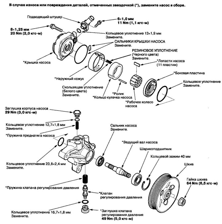
Disassembly
Note: When disassembling, please refer to the exploded view image.
1. Remove the power steering pump.
2. Drain the liquid from the pump.
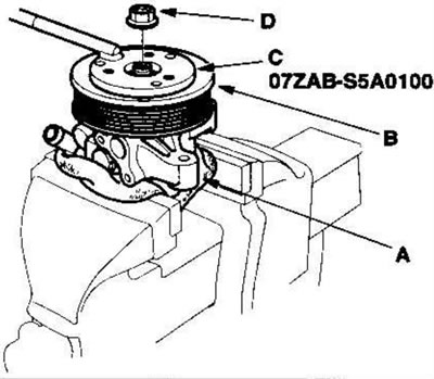
3. Secure the power steering pump (A) in a vice with soft jaws, secure the pulley (B) with the special tool (C), unscrew the pulley nut (D) and remove the pulley (E). Do not damage the pump body with the vice jaws.
4. Unscrew the supply nipple and remove the O-ring.
5. Unscrew the plug from the pressure regulating valve, remove the O-ring, valve spring and pressure regulating valve.
6. Unscrew the plug from the pump body, remove the O-ring and the pump preload spring.
7. Remove the cover from the pump and remove the seals from the pump cover.
8. Remove the roller.
9. Remove the outer casing, pump cam ring, pump impeller, pump vanes and side plate.
10. Remove the rubber seal and sliding seal from the outer casing.
11. Remove the O-rings from the bottom of the housing.
12. Remove the ring clamp, then remove the pump drive shaft by tapping the end of the shaft with a plastic hammer.
13. Remove the seal from the pump body.
Examination
14. Check the groove edges on the pressure regulating valve for wear, scoring or other damage.
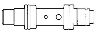
15. Check for scratches or wear on the walls of the pressure regulating valve cylinder in the pump body.
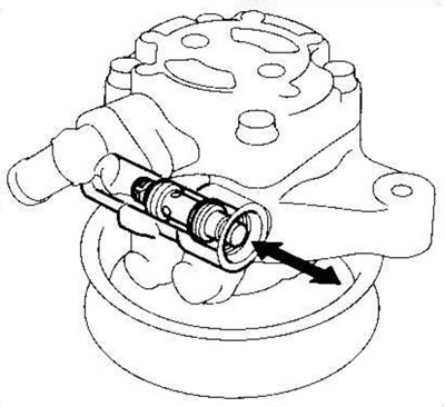
16. Insert the pressure regulating valve back into the pump body and make sure it moves smoothly. If the valve is in good condition, proceed to step. 17; if not, replace the pump assembly. The pressure regulating valve is not supplied separately.
17. Connect the hose (A) to the end of the pressure regulating valve (B) as shown in the figure. Immerse the valve in a container of power steering fluid or solvent (C) and blow into the hose.
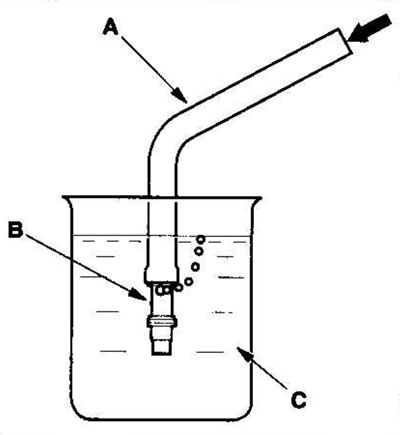
- If the pressure is less than 98 kPa (1.0 kgf/cm²) air bubbles are coming out of the valve, replace the pump assembly. The pressure regulating valve is not supplied separately.
- If the pressure regulating valve passes the test, set it aside for later assembly.
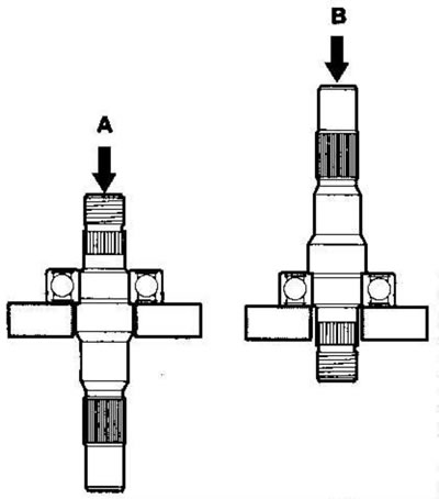
18. Check the ball bearing by slowly turning the outer ring. If there is any play (axial or radial) or jamming, press out the defective ball bearing (A) and press in a new one (B).
19. Check the components marked with an asterisk (*) in the exploded view image; if any of the components are worn or damaged, replace the pump assembly.
Assembly
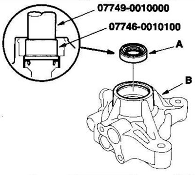
20. Insert the new oil seal (A) (with the groove side facing inward) into the pump body (B), first by hand, then press in using a special tool until the ledge at the top of the seal disappears and the seal is completely seated in the pump body.
21. Insert the drive shaft (A) into the pump body, then press it in using a socket head (B) of the appropriate size, as shown in the figure. Do not exceed the maximum landing force of 1370 N (140 kgf).
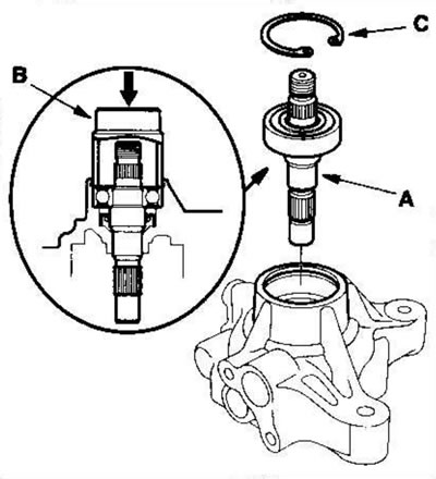
22. Place the 40mm ring clamp (C) with the radius side facing out.
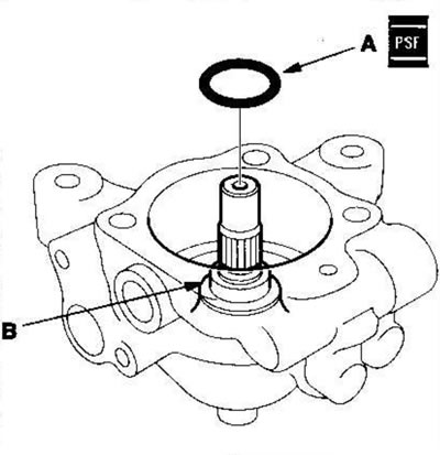
23. Apply power steering fluid to the new 23.8mm O-ring (A), then install it into the bottom (B) of the pump housing.
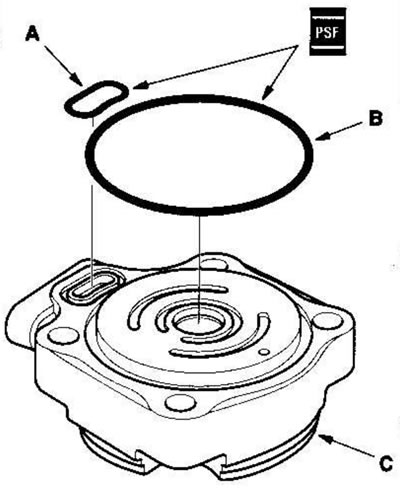
24. Apply power steering fluid to new cover seals (A) and (B), then insert them into the grooves in the pump cover (C).
25. Insert the outer casing (A) by aligning the groove (B) inside the outer casing with the roller hole in the cover (C). Make sure that the slot (D) on the outer casing is installed in the direction shown in the figure.
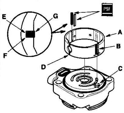
26. Apply power steering fluid to the rubber seal (E) (black color) and insert into the groove (F) on the outer casing.
27. Apply power steering fluid to the sliding seal (G) (white color) and insert it on top of the rubber seal you just put in.
28. Position the pump cam ring (A) with the "•" (dot) mark facing up. Align the groove (B) with the groove (C) on the outer casing.
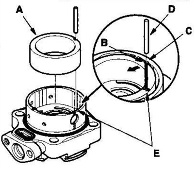
29. Insert the roller (D) into the grooves between the cam ring and the outer casing, then press the roller into the installation hole (E).
30. Place the pump impeller (A) into the cam ring (B).
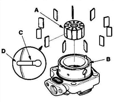
31. Insert 11 blades (C) into the grooves on the wheel. Make sure that the rounded ends (D) of the vanes contact the sliding surface of the cam ring.
32. Place the side plate (A) on the cam ring, aligning the roller mounting hole (B) in the side plate with the end of the roller (C).
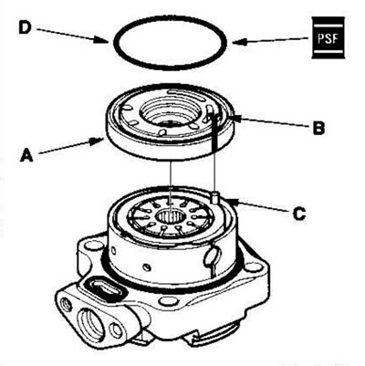
33. Apply power steering fluid to the O-ring (D), then insert it into the groove in the side plate.
34. Place the pump body (A) on the cover assembly (B).
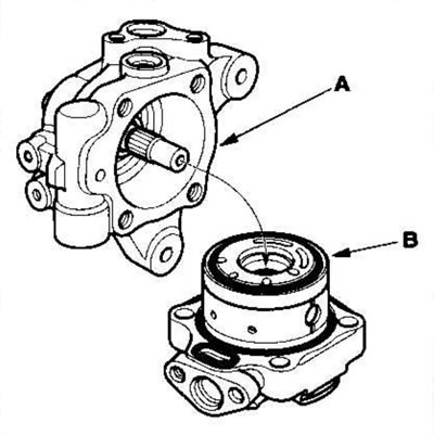
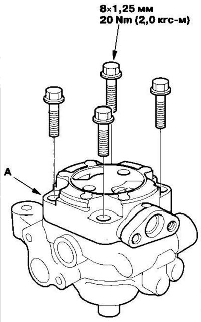
35. Align the bolt holes in the cover (A) with the threaded holes in the pump body. First, start the flange bolts, then tighten them crosswise in two or more passes.
36. Press the cam ring (A) from the plug hole side of the pump housing using a flat-blade screwdriver and make sure that the cam ring is fully seated in the outer casing.
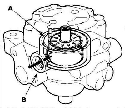
37. Insert the pump preload spring (A) into the pump body.
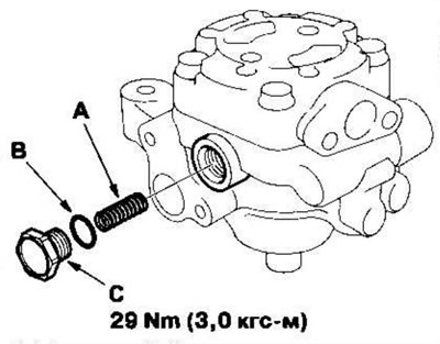
38. Apply power steering fluid to a new 12.7 mm O-ring (B) and insert it into the pump housing plug (C).
39. Insert the plug into the pump body and tighten to the required torque.
40. Insert the pressure regulating valve spring (A) into the pump body.
41. Apply power steering fluid to the pressure regulating valve (B) and insert it into the pump body.
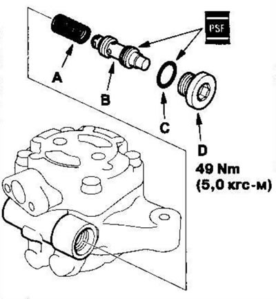
42. Apply power steering fluid to a new 16.7 mm O-ring (C) and insert it into the pressure regulating valve plug (D).
43. Insert the pressure regulating valve plug into the pump body and tighten to the required torque.
44. Apply power steering fluid to the new O-ring (A) and insert it into the inlet fitting (B).
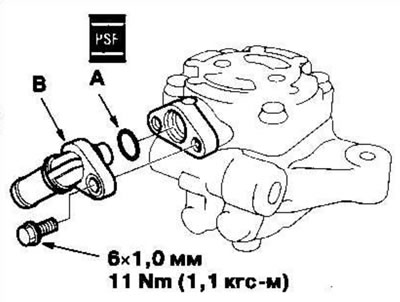
45. Screw the inlet fitting into the pump body.
46. Install the pulley (A), then tighten the pulley nut (B). Secure the power steering pump in a vice with soft jaws. Be careful not to damage the pump body with the vice jaws.
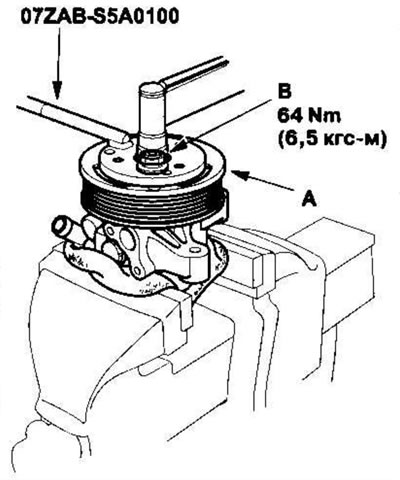
47. Secure the pulley using the special tool and tighten the pulley nut to the required torque.
48. Check that the pump rotates smoothly by turning the pulley. If it rotates with some resistance, loosen the four flange bolts on the cover, then retighten them as in step. 35.